


Product Manager, North America
Automation software with a built-in CNC toolkit enables higher performance and options for cloud connectivity.
Whether designing new systems or updating existing machines in the field, engineers in fabrication environments face pressure to meet production demands for ever-increasing performance and efficiency. Time to market is more abbreviated than ever, and equipment is subject to continual improvements in operation.
To accomplish these objectives, engineers can rely on machine simulation through PC-based automation software. These tools are useful in meeting those challenges, while also providing a range of additional benefits, from higher throughput to longer equipment life.
Open automation software solutions make it possible to program all aspects of machine operation and provide simulation tools by integrating platforms like MATLAB®/Simulink®. This combination enhances the design tools provided by 3D CAD and CNC software. Because of increased programming capability, initial programming is more effective and subsequent adjustments are simpler to implement. Scalable control code can be simulated off the shop floor and then transferred directly to a PC-based controller in the fab shop, which leads to faster retrofits and upgrades.
Simulation corrects many production problems without wasted time and materials by going through trial and error virtually. Beyond the machine, modeling the PLC and fieldbus cycles leads to more effective commissioning and reprogramming of fabricating machines. Even after a new machine is commissioned, these tools can analyze process data to improve performance with minimal downtime. Although the benefits of machine and controls simulation have broad implications for fabrication systems, they are exceedingly clear for CNC machines.
Determining how to cut a part with a CNC always requires careful consideration, whether it’s a waterjet, plasma, laser, or other cutting technology. Engineers determine how to transform workpieces into the desired shape using profiles from the CAD software and CNC software, but many variables—such as excessive plasma flow or laser intensity on corners or curves—remain hidden until run-time. The complexities multiply for each new material type, like when switching from aluminum to stainless steel sheets.
Traditional programming processes are inefficient, wasting engineering time and material. Even after the machine is running, it often requires fine-tuning to reduce waste to acceptable levels.
Simulation with PC-based automation software and third-party simulation software, such as MATLAB/Simulink, first incorporates the existing CAD and CNC models and takes them further. All combined, these can provide 3D CAD models to visualize cutting issues, so engineers can correct them in the code. As a result, the software can run an interpolation, compare the interpolation of the axes, and determine the proper vector based on spline control and the precise measurements of a finished part. With this information, the simulation tools determine the exact part dimensions based on the trajectory of the axis and defined velocities.
For a cutting blade or router, the CNC then “cheats” the axis of the blades when going around corners to offset any blade deflection. For laser, plasma, and waterjet cutting machines, the CNC regulates cutting head intensity, decreasing it when slicing corners and contours to avoid excessive flow and heat concentration. Not only does this decrease part rejects and finishing requirements, but it also improves cut accuracy and energy efficiency. This ensures greater success when adding a new machine or working with new material types, as long as engineers leverage the proper toolkits for virtual machine design and commissioning.
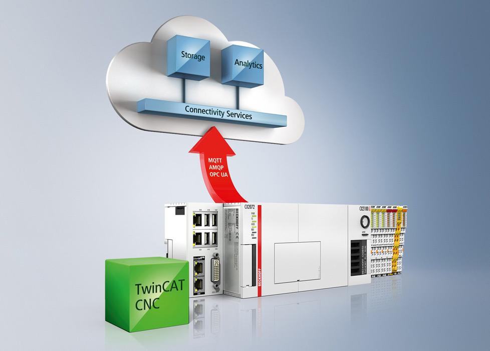
Modern CAD, CNC, and PLC technologies are all key to machine design, but they must converge into a universal platform to build a single effective system. PC-based control provides the optimal platform to encompass all areas of machine automation. One industrial PC (IPC) can run all software for machine control along with any software that runs in Windows.
Choosing the best hardware and software is crucial, because the engineering environment must be able to connect to the simulation software and 3D CAD or emulation system. Meeting these requirements enables so-called software-in-the-loop simulation of the intended sequence on a machine or system to support virtual commissioning.
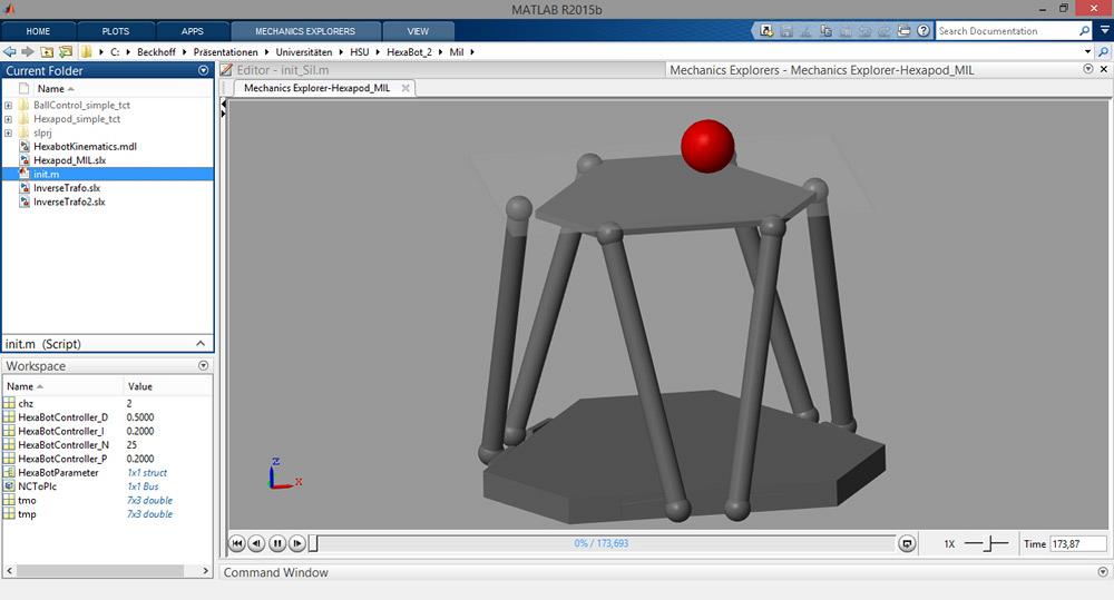
Using MATLAB/Simulink environments, engineers can design and simulate many aspects of new applications, such as this hexapod and the advanced algorithms used in the machine controller.
Linking the machine control to the machine’s CAD model enables full 3D simulation of machines, systems, and installed components based on the real motion and logic controller giving an accurate representation of real-world processes. This link can be accomplished by mapping complex relationships between hardware and software tools. To configure and parameterize links with ease, convenient drag-and-drop functions are available in contemporary simulation software. These functions make both initial commissioning and future system expansions simple and convenient.
In addition, these types of software-in-the-loop simulation connections support 3D representation of each installed component, its movements, and how it interacts with other components. For example, this type of simulation can predict and prevent possible collisions and critical states before they occur. This is on top of more nuanced adjustments, such as raw material quality or laser intensity. However, even better outcomes are possible by simulating more fundamental aspects.
Minute adjustments to motion axes make key differences in throughput, part quality, and energy efficiency, but it is important also to remember factors that fundamentally determine machine performance. Through the same software tools, engineers also can simulate the machine controller and fieldbus or industrial Ethernet system to take programming further away from the shop floor. This offline programming capability provides necessary information for both new machines and continuous improvement efforts to ensure that any small-scale changes are programmed correctly to support the overall system.
Simulation of complex algorithms and motion models is possible through PC-based automation software and the MATLAB/Simulink environment. This simulation supports creation of scalable PLC and CNC code on the engineering PC, and scalable run-time projects for the IPC that will eventually perform machine control, cloud communication, and any other needed functions. The PLC code should be simulated in real time at the same update cycle that will be used during machine run-time. This helps the programmer identify potential issues with timing or “race” conditions. Because engineers do not need the physical controller on hand, they can fully test new applications before purchasing any hardware. This greatly simplifies the industrial component supply chain by minimizing incorrect orders and returns.
Programmers can simulate EtherCAT industrial Ethernet technology with or without the machine controller on hand. EtherCAT is also capable of simulation, even for implementations involving CAN Application Protocol over EtherCAT (CoE) and Servo Drive Profile over EtherCAT (SoE). In this scenario, an engineer does not need to reconfigure the IPC or drives; he or she simply connects the engineering PC to the master controller. If the control hardware has not been purchased yet, simulating the fieldbus in real time is possible by supplying the actual network update rates in MATLAB/Simulink. This provides important information for accurately sizing the controller CPU during virtual commissioning. As a result, engineers can easily change specifications to increase processing power or scale back to a lower-cost device before buying any hardware.
While these methods can ensure that fabrication machinery performs at higher levels from the start, simulation also supports continuous improvement efforts and offers additional benefits for training. After commissioning of a new system or reprogramming of an existing machine is complete, simulation software can continue to make improvements. Reading and writing real-world data from sensors and actuators allows the Simulink model to use information that enables hardware-in-the-loop simulation. This process provides higher throughput and greater repeatability, and it limits machine wear, maintenance time, and downtime.
Simulation also makes it possible to train operators and maintenance staff before commissioning is complete. Sales personnel also can use simulation tools to demonstrate machine features and performance to customers through 3D representations. It is possible to learn about both regular operation and machine troubleshooting using the simulated system.
Matt Prellwitz is drive technology application specialist, and Daymon Thompson is automation product manager, North America, Beckhoff Automation, 13130 Dakota Ave., Savage, MN 55378, 952-890-0000, www.beckhoff.com/twincat3, www.beckhoff.com/cnc.
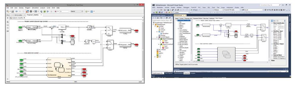
For software-in-the-loop simulation, the intended machine or system processes are first created and simulated in Simulink with drag-and-drop functions to configure and parameterize links, before being run in real time with PC-based automation software (shown in the graphic on the left). When the processes are run on PC-based automation software in real time at real process update rates, Simulink continues to monitor machine or system performance through the digital link, connecting it to the controls engineering environment and 3D CAD or emulation system (shown in the graphic on the right).


The Fabricator is North America's leading magazine for the metal forming and fabricating industry. The magazine delivers the news, technical articles, and case histories that enable fabricators to do their jobs more efficiently. The Fabricator has served the industry since 1970.
start your free subscription
Easily access valuable industry resources now with full access to the digital edition of The Fabricator.

Easily access valuable industry resources now with full access to the digital edition of The Welder.

Easily access valuable industry resources now with full access to the digital edition of The Tube and Pipe Journal.

Easily access valuable industry resources now with full access to the digital edition of The Fabricator en Español.
In this episode of The Fabricator Podcast, Caleb Chamberlain, co-founder and CEO of OSH Cut, discusses his company’s...


