


Contributing Writer
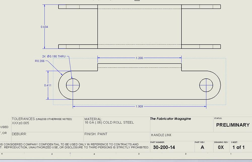
Figure 1
A tolerance block in a drawing border specifies the tolerance. The drafter/designer should make sure that it makes sense. For example, could the R0.206 be ±0.030 in.?
“The drawing specifies cost,” says the Spout of Wisdom.
“Well, duh!” replies the Estimator of Cost.
“My drawing specifies need,” drolls the Drafter of Drawings.
Production expenses cover requirements from the drawing, of course. The material, size, and finish all matter. Tolerance is among those cost-driving details.
Ridiculous tolerances are wasteful. Designers/drafters should specify practical tolerances. Fabricators/estimators should report waste and suggest better tolerances when setting budgets in their bids. If everyone understands that, why do silly tolerances continue to appear on drawings?
“Reasonable tolerance” is hard to standardize, and designer/drafters don’t have time to interview all possible production lines. Estimators of Cost are harassed by nature, and Drafters of Drawings are not always receptive to ideas from Purchasers of Parts, who coddle suggestions from Estimators of Cost who know nothing of design.
A tolerance study is among the final actions taken during product development. When the product’s specification is in a “shape-changing stage” of development, the method of manufacture is not the highest priority. As a result, the default CAD template emerges as desire in place of reason until time is taken to study the functional tolerance requirements. A well-reasoned tolerance study is recommended for every drawing.
The guiding light behind a tolerance study and determining final specifications is generosity. Larger, more forgiving tolerances lead to more acceptance. More acceptance basically means less scrap, better yield, and less waste.
Sometimes functional requirements prohibit generosity in tolerance. Sloppy gap and fit are usually disparaging attributes. A demand for consistency part-to-part might dictate a particular method of fabrication. Perhaps a whittling process is arty but too individual; injection molding is the only way to achieve the needed repeatability.
At another extreme, in certain situations (for example, prototypes) the practical tolerance is driven not by the product’s function so much as by what’s available. Speed is the need. As long as it looks like something, it is good. Tolerance-free parts are seldom production items, however.
Hurray for job shops! As a method of production, job shop batch building is agile. Production can adapt to demand very quickly. Not having to carry the expense of capital equipment for fabrication is a blessing to their customers. Accordingly, the product may be intentionally designed to be suitable for any of several production facilities. A design intent suitable for job shopping must accommodate rather generic tolerances.
Please consider the callout ±0.005 shown in Figure 1. Depending on the manufacturing process, such a specification could be routine or ridiculous.
Here’s a CAD tip: Set up document templates for specific fabrication processes so that the design work is launched with “probably practical” tolerance defaults. The production line’s quality assurance crew is the best source of data when setting up templates.
Here is an estimator’s tip: Help the CAD team set up their templates. Prepare a document that states your recommended alloys, finishes, and tolerances by process. Share that document so that as many designers as possible can be informed of the practical tolerances for your facility.
The capability of a process to repeat limits its ability to satisfy any tolerance specification. A method to discover the tolerance capability of a process is to build a database of results. Record the difference between expected and achieved locations for holes and bends. Record the corresponding magnitude of the dimension as well. Collecting the data over time is vital, but the important activity is the review and corrective action. Observe the amount of difference from perfect. Observe where the best and worst results occur. The process may repeat within 0.004 inch over a distance of 1 in. but only within 0.012 in. over a distance of 48 in. Backlash in servo drives may result in rhombus instead of rectangle, oval instead of circle. The recorded inspection data will identify worn machinery, bad clamping systems, bad nesting plans, and other related trends in performance.
Spouted Wisdom: Your customers may not be interested in receiving a record of inspected dimensions, but you certainly are. If you think you can routinely ship ±0.02 but are actually shipping far better (±0.003), you may have an opportunity to improve cash flow. Everything you do to reduce your customer’s receiving inspection gives your relationship with your customer a competitive advantage.
The best source of information regarding capability is from the production line that will be manufacturing the product. If that information is not available, prediction of repeatability is the next best alternative.
Rigidity matters. Repeatability of the process is limited by the machinery’s design, condition, tooling, and clamping. In general, CNC machinery will repeat within 0.004 in. and manual machinery within 0.006 in.
A machine’s datasheet—its advertised capability—is a starting point for predicting capability and practical tolerance. It does not translate into a recommended tolerance on a drawing.
As the temperature changes, coefficients of expansion will result in size variation in the machine’s frame, the tooling, and the workpiece. Temperature may become an issue with tolerances less than 0.001 in. The sharpness of the tool bit, along with its flexibility, will contribute randomness. As with temperature variation, this is a diminutive effect.
As material is removed, the workpiece loses rigidity. This can have a dramatic effect on repeatability. As a consequence of flexibility, the last few cuts have the worst variation. Both the designed tolerance and the production method might require planning for the sequence of material removal.
In a temperature-controlled environment with obsessive process management, repeatability measured in angstroms is achievable. Such process control results in significant expense. When optical or clockwork-type mechanisms are being made, the expense may be justified. When the product absolutely must fit, then absolute process control makes sense.
Thin sheet metal that is welded and sanded manually for lovely appearance is not generally suitable for clockwork tolerance. Overly tight tolerances result in expense because of the low yield rate of the process. In other words, many lovely items are discarded in search of the few that satisfy the dimensional specification.
As an example of a tight generic tolerance in the sheet metal business, consider this guidance: “TOLERANCES UNLESS OTHERWISE NOTED: HOLE-TO-HOLE: ±0.006 in., HOLE-TO-FOLD: ±0.010 in., FOLD-TO-FOLD: ±0.14 in., ANGLES: ±0.125 degrees.”
That tolerance is an example of precision in sheet metal. To achieve this promise, the production line—shearing, punching, and bending—must repeat within 0.004 in., and the workpiece has to be rigid enough not to lose 0.002 in. while it is being handled. Welding easily can vary 0.010 in. over 2 in. Manual sanding and grinding is variable by 1/32 in. or more.
Larger tolerance means less scrap and less expense. Here is an improved generic sheet metal callout: “TOLERANCES UNLESS OTHERWISE NOTED: HOLE-TO-HOLE: ±0.010 in., HOLE-TO-FOLD: ±0.012 in., FOLD-TO-FOLD: ±0.020 in., ANGLES: ±0.25 degrees.”
Your comments on practical tolerances for various processes are appreciated. Fabrication happens in many predictable ways: casting, molding, additive machining, laser, waterjet, stamping, punching, fully CNC machining, and fully manual machining.
In the next episode we’ll review techniques in 3D CAD for populating tolerance blocks on drawings, as well as some examples of interference detection and tolerance analysis.
Gerald would love for you to send him your comments and questions. You are not alone, and the problems you face often are shared by others. Share the grief, and perhaps we will all share in the joy of finding answers. Please send your questions and comments to dand@thefabricator.com.


The Fabricator is North America's leading magazine for the metal forming and fabricating industry. The magazine delivers the news, technical articles, and case histories that enable fabricators to do their jobs more efficiently. The Fabricator has served the industry since 1970.
start your free subscription
Easily access valuable industry resources now with full access to the digital edition of The Fabricator.

Easily access valuable industry resources now with full access to the digital edition of The Welder.

Easily access valuable industry resources now with full access to the digital edition of The Tube and Pipe Journal.

Easily access valuable industry resources now with full access to the digital edition of The Fabricator en Español.
In this episode of The Fabricator Podcast, Caleb Chamberlain, co-founder and CEO of OSH Cut, discusses his company’s...


