


Contributing Writer
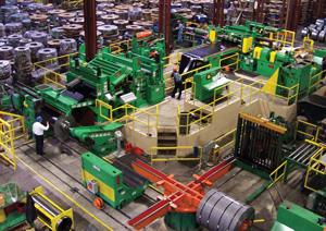 |
A common theme among fabricators and service centers is that slitting steel has become a commodity process with very low margins. Considering the staggering amount of manufacturing that has moved overseas recently, it follows that too many slitting lines in the U.S. are chasing too small a market—or, simply put, the slitting market has too much capacity. Carbon steel has been hit the hardest because it requires less advanced technology and often can be processed using unskilled, low-cost labor.
To maintain a manufacturing sector in this country, industry must continually improve in efficiency. Manufacturers and processors can and should specify new machines that run at high speeds and allow quick setups, which are two essential ingredients for efficient operation. If a new slitting line is not in the cards, however, many existing slitting line components can be upgraded to improve efficiency.
Choosing the right components does not necessarily mean choosing the most expensive ones. Coil processors should choose components that match the type of products run, the frequency of setup changes, and the labor available to operate the line. Some of the aspects that affect slitting line efficiency are entry coil storage; coil inside diameter (ID) changes; slitter tooling changeover; scrap handling; and strip tensioning.
A good entry coil storage system can improve efficiency by reducing line downtime and by allowing efficient use of overhead cranes. The ability to stage multiple coils is crucial because it prevents waiting at the line, and it allows the crane operator to retrieve and load coils whenever it is convenient, not when it is necessary. Common coil storage devices are turnstiles, saddles, and turntables.
Turnstiles with four arms are suitable for many slitting line applications. Because they rotate, they allow the line operator to select any coil in any order. However, they support coils by the ID, and may damage thin, heavy coils. Also, it can be difficult to load small-ID coil.
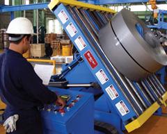
Storage saddles (see Figure 1) support coils from their outside diameter (OD). This design eliminates ID damage on heavy coils and allows easy loading from an overhead crane. The drawback is that saddles usually are placed in a straight line, which requires the operator to select the coils in consecutive order.
Storage turntables have the advantages of turnstiles and saddles. A storage turntable is composed of saddles, so it eliminates the risk of ID damage. The saddles are mounted on a turntable, so the operator can select the coils in any order. This design usually requires a pit-type coil-loading car or a very low-profile scissor lift car.
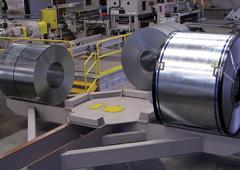 |
| Figure 1 Using storage saddles for staging heavy coils eliminates ID damage. |
 |
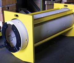
| Figure 2 Filler rings allow an uncoiler to handle large-ID coils safely. |
 |
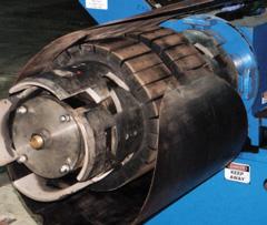
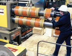
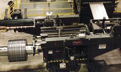
| Figure 3 Inexpensive slitter heads can be removed by crane, but require careful handling. |
 |
| Figure 4 Turret slitters provide easy access to slitter tooling during offline setups. |
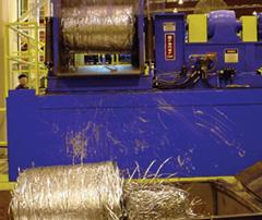 |
| Figure 5 Scrap ballers efficiently process light-gauge scrap into tight, compact balls. |
Expanding-mandrel uncoilers have a limited expansion range, meaning they might handle coils from 16 inches to 20 in. or from 20 in. to 24 in. ID without filler plates. If the operator needs to run coils with a larger ID than the uncoiler was designed to handle, some type of filler plate is required. Loading and removing these filler plates can cause quite a bit of downtime. Two very different designs are available, but their efficiency depends on how frequently they are used.
Filler rings, sometimes called doughnuts, are an inexpensive way to run larger-ID coils (see Figure 2). They have no range, meaning they can handle a single size only, such as a 29-in. ID. Rings are best for occasional use only because, even though they can be loaded fairly quickly, they have to be loaded into each and every coil run.
Bolt-on filler plates can be time-consuming to load, but for multiple coil runs they tend to be more efficient because they stay on the drum and do not need to be loaded into each coil. They also provide the same expansion range as the base drum, which means they could be designed to handle 28-in.- to 32-in.-ID coils, for example, on a 20-in. to 24-in. drum. The plates can be made from plastic for ease of handling or from steel for durability. Newer designs include a speed loading fixture and use tabs instead of bolts. This type of design allows the plates to be mounted on an uncoiler in less than five minutes.
Manufacturers have embraced just-in-time (JIT) delivery for reducing inventory, but it creates a production nightmare, especially as low-volume runs have become commonplace. Operating a line efficiently requires quick-change slitter heads. Having more than one head allows the operator to change the tooling offline while the machine is running. Several methods for changing heads are available, with cost, floor space, and crane time primary considerations.
Removable-head slitters that lift off by crane are the least expensive approach to offline tooling changeover (see Figure 3). This method is time-consuming, though, because personnel must remove mechanical fasteners and the crane might not be available immediately. Operators must use extreme care—a removable head is a heavy piece of machinery, so this activity has some risk.
Injector-head slitters that shuttle in and out of the line on rails are more expensive, but operators can change them safely in as little as two minutes. This design requires a fair amount of space and may block the operator's view of the line.
Slitter knife transfer units hold the tooling offline on rotating arms and use a mechanical pusher to slide the tooling onto the arbors. This design, which resurfaced recently, was patented in 1970 and was intended to speed tooling changes on fixed-head slitters. The main drawback is that the tooling can bind up during transfer.
Another design known as a turret-head slitter (see Figure 4) evolved from the original knife transfer unit and allows safe, two-minute head changes at a reasonable cost. No space is required on the operator side of the line, and the design provides easy, ergonomic access to the slitter tooling.
Many people view the handling of scrap edge trim as a necessary evil, with the only consideration given being ways to minimize scrap and thereby maximize yield. If handled poorly, however, scrap edge trim can cause excessive downtime in slitting lines. Three major systems exist for handling scrap. The efficiency of each type is determined for the most part by the coil thickness range the line will run.
With a scrap baller system, the slitter head drives the edge trim into an accumulation pit. Later, usually after the coil has finished running and the line has actually stopped, the scrap baller pulls the edge trim from the pit under zero tension and uses a steel mashing roll to force it into a compact ball (see Figure 5). This design is most efficient for material from 0.005 in. to 0.187 in. thick because zero tension means fewer scrap breaks, and the operator is not distracted by scrap during line run. To operate properly, scrap ballers do require a fairly large accumulation pit.
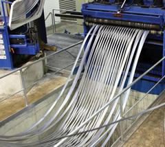
Scrap winders pull the scrap under tension from the slitter head while the line is running. It is advantageous to install them in pairs to maintain uniform tension on each scrap strand. This design works for material from 0.010 in. to 0.500 in. thick, but is best-suited for medium gauges up to 0.250 in. thick because light-gauge scrap has a tendency to break and heavy-gauge scrap is difficult to thread. The line operator must pay attention to the scrap and maintain tension at each winder during line run.
Scrap choppers are located directly after the slitter head and have custom tubes or chutes that allow self-threading. Scrap choppers can accommodate material from 0.010 in. to 0.750 in. thick, but are best-suited for heavier gauges because frequent knife maintenance may be required when cutting thin material. This is the most expensive type of scrap handling system, but the higher value of the chopped scrap may help justify the cost.
To ensure proper tracking in a rolling mill, flat rolled coils are produced with a crown—the center of the strip is thicker than the edges. When slitting a coil, the thicker mults in the center rewind to a larger diameter than the thinner mults at the edges. Years ago slitting lines ran only in tight-line mode. To wind each slit coil tightly, the operator would have to stuff pieces of paper or cardboard into the thinner mults to make them the same diameter as the thicker mults. This mode of operation was not only dangerous, but it also induced camber in the outside mults because they were fanned out at an angle for separation after slitting and then bent straight under tension at the recoiler drum.
The addition of a looping pit and tension stand into slitting lines is still one of the greatest advances in technology (see Figure 6). Loop slit operation allows the line to produce tight coils and straight side walls without the danger of stuffing cardboard and without the quality issues resulting from camber induced during tight-line operation.
 |
| Figure 6 UA looping pit/tension stand combination eliminates the hazardous practice of "stuffing" cardboard into coils. |
 |
| Figure 7 Special fixtures load filler plates onto the recoiler drum in less than five minutes for quick ID changes. |
 |
| Figure 8 Turret recoilers provide a safe and practical method to band coils offline. |
 |
| Figure 9 Traversing downenders eliminate ID damage caused by pushing coils. |
The real trick to loop slitting is to apply the required amount of back tension without damaging the strip—and without spending a fortune on tension stand consumables and maintenance. Several tensioning methods exist, but the most appropriate machine depends on the type of material run.
Pad-type tension stands use felt-covered boards to apply tension to the strip. The felt is available in a variety of thicknesses and densities to suit various material conditions. An air bladder can be used, but a series of cylinders applies the clamping pressure more evenly across the boards. These machines are simple in design, so they are among the least expensive to purchase, and the felt is relatively inexpensive, so they are among the least expensive to maintain. Using a Velcro®-type attachment system allows quick changes, and a large board size reduces strip damage by spreading the clamping force over a large area.
Rotary tension stands use rolls to apply tension to the strip. Because the rolls rotate at approximately the same speed as the strip, rotary tension stands reduce scratching and usually are preferred for surface-critical material. Cylinders or screw jacks clamp the rolls, and the braking force can come from a water-cooled brake or an electric drag generator. Polyurethane rolls work well on dry strip, and nonwoven fabric rolls work well on oily strip. Roll changes can be accomplished quickly with lift-off cartridges, but newer duplex designs save space and allow roll changes in as little as two minutes.
In another concept for tensioning, a roller leveler elongates, or stretches, some of the slit mults to reduce the apparent strip length differential and, therefore, reduce the need for a looping pit. This method can be effective for slitting lines that would require a shallow looping pit, but stretching the mult also reduces its width, a phenomenon known as necking. Necking becomes more severe as the pit requirement becomes deeper because more stretching has to occur. In some cases, the mult width can be reduced by 0.040 in. or more. In theory, machine operators can adjust the tooling on the slitter to compensate for the width reduction, but this assumes that the amount of strip crown is known and the strip crown is consistent throughout the coil.
The actual depth of looping pit required depends on two factors: the length of material in the coil and the difference in thickness between the thinnest and thickest mults. One formula to calculate approximate pit depth is:
Pit Depth = (OD - ID)2 * (T - t) * 3.14
(96 * T2)
Where:
OD = coil OD in inches
ID = coil ID in inches
T = maximum strip thickness
t = minimum strip thickness
Exit Coil ID Changeover
Recoiler drums expand and collapse just enough to allow coil removal, and so they produce just one coil ID size. To produce a variety of ID sizes requires filler plates or interchangeable drums. Changing these plates or drums can cause quite a bit of downtime.
Bolt-on filler plates are available in plastic or steel, but coil processors don't have a choice—steel is required—if no coil car is used to relieve the coil's weight as the coil is pushed off the drum. Some filler plate designs have a fixture to aid in loading, but even with a fixture, installation can be time-consuming. Newer designs have a speed-loading fixture and tabs instead of bolts (seeFigure 7) so operators can mount the plates on the recoiler in less than five minutes.
Interchangeable recoiler drums also can change the coil ID. This method is more expensive than filler plates, but it eliminates the long tail inherent with filler plate designs. New interchangeable drums feature a quill-type shaft that mounts in a hollow bore reducer. Operators can exchange this type of drum without tools in less than five minutes.
Banding the OD of slit coils is one of the most time-consuming and inefficient aspects of slitting. This operation usually is performed on the recoiler drum before the coil is pushed off, meaning the line is down until banding is finished. If slit coils will be used in-house and do not have to be shipped, glass filament tape is suitable for dry, light-gauge material, and tack welding works for heavy, hot-rolled material. Regardless of the banding method, a tail hold-down clamp should be included with the overarm separator to secure tails and prevent them from slipping during banding.
Special clamps for the exit coil car or exit turnstile allow offline OD banding. Unfortunately, most of these clamps work better in theory than they do in practice. The coil must be clamped and unclamped several times, which increases the risk of slipping and the high-back design of most coil cars makes the banding operation virtually impossible on this type of machine.
Turret recoilers equipped with two complete drums, overarm separators, and tail hold-down clamps are very expensive, but they provide the safest, most reliable method of offline banding (seeFigure 8). In cases where many narrow cuts are made or coils are broken down two to three times for weight, turret recoilers can literally double line productivity and efficiency.
If not handled properly, the process of packaging slit coils for shipment can create a major bottleneck and ruin the efficiency of a slitting line. Packaging lines range from manual to fully automated, with cost directly proportional. To determine system needs, coil processors should try to estimate the number of mults the slitting line produces in an hour. If the number is less than 30, a manual system will probably do just fine. If the number is more than 30, some automation should be considered. Key areas of slit coil packaging that can be automated to improve efficiency include downending, radial banding, and stacking.
A downender takes the slit coils from the turnstile and lays them down one by one so they are facing eye to the sky. Manual downenders are the least expensive design but are labor-intensive. They also require a pusher on the turnstile that can damage the inner wraps of the coil. Traversing or pick-and-place downenders are programmable, so no operator is required during operation (see Figure 9). No pusher is required because they traverse to the coil for pickup, which eliminates damage to inner wraps and allows pickup of very narrow coils.
To prevent damage during transit, radial (ID to OD) banding is required for most coils. The least expensive approach is to band the coils manually using hand tools, but this can be labor-intensive and slow. Semiautomatic banding machines have moderate cost and fairly quick operation, but still require an operator. Fully automatic banding machines do not require an operator but are more expensive, not necessarily faster, and may require complex maintenance.
Stacking coils for shipment can be handled manually with an ID coil grab that hangs from a monorail or jib crane. Coils are stacked on pallets on the floor, making this a somewhat slow but economical process. The next step up is an automatic coil grab that picks up the coil and transports it to a carousel. This design, known as a wagon stacker, provides good productivity at a moderate cost. For the ultimate speed and throughput, though, turret-head stackers combine two independent grabs on a rotating turnstile. While one head is picking up a coil, the other head is setting one down. This design is essentially twice as fast and twice as efficient as any other.
Want more information?<<<<<<<< If you are interested in a basic look at coil processing, read "The basics of uncoiling" |
The last, but certainly not least, important component for improving slitting line efficiency is staffing and training. Every slitting line, even one that is highly automated, requires proper staffing—enough people with enough training—to operate at peak efficiency. Quick-change slitter heads improve efficiency only if they are tooled up and ready to go. New lines operate very differently from conventional machines, which makes training essential for new lines. A good preventive maintenance program also increases productivity and reduces downtime. Maintenance personnel should be more than emergency repairmen.
Like it or not, slitting lines, like many manufacturing operations, are now competing with low-cost operations on a global scale. Excellent quality and service alone do not guarantee profit or survival. To remain competitive, coil processors must operate their slitting lines at peak efficiency. Keeping a close eye on the main areas that affect slitting line efficiency, and using the most suitable equipment in those areas, combined with proper staffing and training, can help coil processors remain competitive in an increasingly competitive industry.
Kenneth F. Shoop is southeast regional manager of Braner USA Inc., 9301 W. Bernice St., Schiller Park, IL 60176, 847-671-6210, fax 847-671-0537, branerusa@braner.com, www.braner.com.

The Fabricator is North America's leading magazine for the metal forming and fabricating industry. The magazine delivers the news, technical articles, and case histories that enable fabricators to do their jobs more efficiently. The Fabricator has served the industry since 1970.
start your free subscription
Easily access valuable industry resources now with full access to the digital edition of The Fabricator.

Easily access valuable industry resources now with full access to the digital edition of The Welder.

Easily access valuable industry resources now with full access to the digital edition of The Tube and Pipe Journal.

Easily access valuable industry resources now with full access to the digital edition of The Fabricator en Español.
In this episode of The Fabricator Podcast, Caleb Chamberlain, co-founder and CEO of OSH Cut, discusses his company’s...


