Contributing Writer
- FMA
- The Fabricator
- FABTECH
- Canadian Metalworking
Categories
- Additive Manufacturing
- Aluminum Welding
- Arc Welding
- Assembly and Joining
- Automation and Robotics
- Bending and Forming
- Consumables
- Cutting and Weld Prep
- Electric Vehicles
- En Español
- Finishing
- Hydroforming
- Laser Cutting
- Laser Welding
- Machining
- Manufacturing Software
- Materials Handling
- Metals/Materials
- Oxyfuel Cutting
- Plasma Cutting
- Power Tools
- Punching and Other Holemaking
- Roll Forming
- Safety
- Sawing
- Shearing
- Shop Management
- Testing and Measuring
- Tube and Pipe Fabrication
- Tube and Pipe Production
- Waterjet Cutting
Industry Directory
Webcasts
Podcasts
FAB 40
Advertise
Subscribe
Account Login
Search
Deep drawing irregular sheet components: How cushion systems and die stiffness affect the operation
- By Prof. Dr.-Ing. H.c. Klaus Siegert
- April 24, 2001
- Article
- Bending and Forming
The goal of deep drawing irregular sheet metal components is to make products with the desired quality at competitive costs. To reach this goal, the press technique and the tool and die technology have to be optimized to achieve a productive, reproducible forming process.
Steering Sheet Metal Flow
A main objective when deep drawing irregular components such as automotive fenders or decklids is that the sheet metal flowing between the binders of the draw die has to be steered properly, causing no wrinkles and cracks.
To steer the sheet metal flow between the binders of the draw die, one or a combination of the following methods can be used:
1. Draw beads. Draw beads can hinder the metal flow in certain areas of the blank holder by causing bending and friction forces. Height-steerable draw beads can be adjusted in the binders to steer the amount of the metal flow hindrance over the stroke.
2. Lock beads. Lock beads can stop the metal flow entirely in a specific area of the binders. They can be steered up at a certain stage of the forming process after allowing the sheet metal to flow easily into the cavity of the draw die without hindrance from the lock beads.
This shape set in one operation helps to increase the product's shape accuracy, especially if the material is difficult to form, such as aluminum or high-strength steel is.
3. Shape of the blank. A local increase of the blank size causes higher forming and friction forces, thus hindering metal flow between the binders.
4. Friction between the blank and the binders. Friction forces can be changed to steer the metal flow between the binders. Three methods typically are used to increase or decrease the friction forces--Narrowing or widening (fitting in) the gap between the binders, spraying more or less lubricant on the blank, and changing the pressure between the blank and the binders.
Hydraulic Cushion Systems
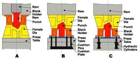
The deep drawing process can be done in a double-acting press with two rams (main ram and blank holder ram) (see Figure 1A) or in a single-acting press with a cushion system in the press table (see Figure 1B). Both types of presses can be mechanically or hydraulically driven.
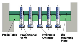
Double-acting presses are used most often for deep drawing. In some single-acting presses, hydraulic cylinders are installed at the four corner points of the press table (see Figure 1C). Each cylinder has its own proportional or servo valve so that specific blank holder forces can be run over the stroke for each cylinder.
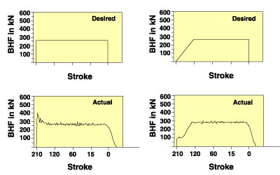
The blank holder pressures can be controlled individually, allowing different pressures for front left, rear right, etc. The four blank holder forces act directly on the blank holder. With this system, an ascending ramp can be programmed (see Figure 2) to prevent a peak of the blank holder force when the upper binder hits the blank on the lower binder (blank holder). It also helps to make the forming process more reproducible by programmable blank holder forces over the stroke.
More on Hydraulic Cushion Systems
For larger dies in transfer presses, multipoint cushion systems typically are used. In these systems, the cushion plate is supported by four, six, or eight hydraulic cylinders. The pressure in each cylinder is built up by compression when the cushion plate is forced downward and steered by a corresponding proportional or servo valve.
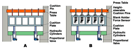
The blank holder forces are transmitted from the cushion plate to the blank holder of the die by several cushion pins (see Figure 3A). The only way to increase the blank holder pressure in a certain area is to put little pieces of sheet between the blank holder and the corresponding cushion pin, but this makes process reproducibility difficult.
A recently developed hydromechanical multipoint cushion system (see Figure 3B) has CNC height-adjustable cushion pins. Each cushion pin has its own load cell to monitor the blank holder forces, which are introduced to the blank holder.
This cushion system makes it possible to adjust the blank holder forces point by point over the stroke. This can help to decrease the time needed for tryout of new or redesigned dies, and it widens the working range of the blank holder force over the stroke between the point at which wrinkling occurs and the point at which tearing occurs.
An alternative multipoint cushion system is shown in Figure 4.
Here, a number of hydraulic cylinders, each steered by its own proportional or servo valve, act directly on the blank holder of the draw die. As with the system shown in Figure 3B, this system also allows point-by-point adjustment of the blank holder pressure.
Both the multipoint cushion systems shown in Figure 3B and in Figure 4 need elastic blank holders for point-by-point adjustment. The distance between the pins of the system shown in Figure 3B can be as little as 300 millimeters. The distance between the hydraulic cylinders of the system shown in Figure 4 usually must be greater than 400 millimeters.
Die Flexibility
Normally, dies are built to be rigid rather than flexible. However, they cannot and should not be absolutely rigid.
When using a CNC multipoint cushion system, such as those shown in Figures 3B and 4, each cushion pin can be used to influence a corresponding defined area of the lower binder surface. This action can be optimized with a segment-elastic blank holder (SE-BH), designed by the Institute for Metal Forming Technology (IFU) of the University of Stuttgart.
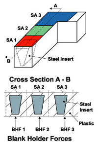
The blank holder can be made from a nylon-based thermoplastic material and designed with pyramid-shaped steel inserts (see Figure 5). The blank holder forces are introduced into the pyramid-shaped steel inserts (top down), so there is a clear correspondence between the blank holder force and the pressure-influenced base area of the pyramid. For example, the surface area SA 2 of the blank holder is influenced by the blank holder force BHF 2 in Figure 5.
Between the stiff steel inserts, the flexible plastic material acts like elastic links. This makes it possible to get a specific pressure in a certain, clearly defined blank holder area without influencing the neighboring blank holder areas.
Another version of the SE-BH was designed in cast steel with stiff pyramids and elastic steel links (seeFigure 6). As with the plastic binder shown in Figure 5, a direct relationship exists between the pressure of each area of the blank holder surface and a corresponding pin force. With this kind of blank holder, the metal flow between the binders can be steered area by area by adjusting the corresponding blank holder forces, without influencing the neighboring blank holder pressures.
Die Flexibility II
Finite element method (FEM) calculations showed that the height of the blank holder should be equal to the distance between the pyramids. The blank holder pressure is influenced not only by the ribbing of the lower binder (blank holder), but also by the stiffness of the upper binder. To keep the positive effects of the SE-BH, which is the lower binder, the vertical stiffness of the upper binder has to be high and equally distributed.
Figure 7shows some binders with thick vertical ribs and large distances between. Both ribbings shown in this figure result in different stiffnesses over the binder. This makes it necessary to fit in the distances between the binders by hand.
The newly developed prismatic ribbing for the upper binder also leads to a high and equal distribution of the stiffness over the binder. Prismatic ribbings (see Figure 8) are characterized by a tight and regular pattern of ribs. On the side of the blank holder, a plate closes the cavities. On the side of the ram, the cavities stay open. A draw die with a prismatic design has low weight and high vertical stiffness.
When an SE-BH is used with a prismatic ribbed upper binder, a multipoint cushion system can be integrated into the draw die. This allows an adjustment of individual blank holder forces over the stroke for each hydraulic cylinder by corresponding proportional or servo valves. Not only can cylinder position be optimized, but so can the number of cylinders per die. This die concept needs only a single-acting press with no cushion system in the table of the press and is suitable for high-volume production.
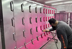
Nitrogen cylinders can be used instead of hydraulic cylinders. The lead photo shows a draw die with an SE-BH and pressure-steerable nitrogen cylinders for an automotive structure part. Here, the pressure of each blank holder area can be adjusted separately.
Achieving a Reproducible Process
All of these examples of the newly developed blank holder design and the upper binder design in single-acting presses with multipoint cushion cylinders in the press table or in the die can help fabricators to achieve a reproducible, efficient deep-drawing process, which aids forming of difficult materials, such as high-strength steel sheets and aluminum sheet.
References
R. Kergen,"Computerized control of the BHF in deep drawing," in proceedings from IDDRG '95 meeting, Comar, France, 1995, pp. 22-24.
M. Klamser, "Ziehen von Blechformteilen auf einfachwirkenden Pressen mit hydraulischer Zieheinrichtung im Pressentisch, Diss. 1994," Beitrge zur Umformtechnik, Hrsg. K. Siegert (DGM-Informationsgesellschaft mbH).
F. Schneider, "Steuerung des Kraft-Weg-Verlaufs beim Umformen, dargestellt an der Ziehstufe einer Groteilstufenpresse," Ziehtehnik auf der Groteilstufenpresse, Hrsg. E. Doege (HFF-Bericht Nr. 11, 1987), pp. 99-114.
F. Schneider, "Ausgefhrte hydraulische Zieheinrichtungen der Fa. Schuler und Zielsetzungen fr die Zukunft," Zieheinrichtungen einfachwirkender Pressen in der Blechumformung, Hrsg. K. Siegert, (DGM-Informationsgesellschaft mbH, 1991).
K. Siegert, "CNC hydraulic multipoint blank holder system for sheet metal forming presses," Annals of the CIRP, Vol. 42/1/1993, pp. 310-322.
K. Siegert, J. Hohnhaus, and S. Wagner, "Combination of hydraulic multipoint cushion systems and segment-elastic blankholders," SAE paper 980077.
K. Siegert et al, "Multipoint cushion systems for sheet metal forming presses," The FABRICATOR, February 1999, pp. 82-86.
About the Author
subscribe now

The Fabricator is North America's leading magazine for the metal forming and fabricating industry. The magazine delivers the news, technical articles, and case histories that enable fabricators to do their jobs more efficiently. The Fabricator has served the industry since 1970.
start your free subscription- Stay connected from anywhere

Easily access valuable industry resources now with full access to the digital edition of The Fabricator.

Easily access valuable industry resources now with full access to the digital edition of The Welder.

Easily access valuable industry resources now with full access to the digital edition of The Tube and Pipe Journal.
- Podcasting
- Podcast:
- The Fabricator Podcast
- Published:
- 04/16/2024
- Running Time:
- 63:29
In this episode of The Fabricator Podcast, Caleb Chamberlain, co-founder and CEO of OSH Cut, discusses his company’s...
- Industry Events
16th Annual Safety Conference
- April 30 - May 1, 2024
- Elgin,
Pipe and Tube Conference
- May 21 - 22, 2024
- Omaha, NE
World-Class Roll Forming Workshop
- June 5 - 6, 2024
- Louisville, KY
Advanced Laser Application Workshop
- June 25 - 27, 2024
- Novi, MI


