


Contributing Writer

When I conduct a training course, I usually bring along an assortment of stamped parts. The ones attendees examine most are those made with a multiple-step drawing process, commonly referred to as a draw reduction.
Drawing is the displacement of metal through plastic flow or inward feeding. In draw reduction, a series of drawing operations gradually displaces the surface area of a blank into a geometry that is smaller in diameter and taller than each of the previous stations.
For the metal to flow inward and be displaced into a different geometry, each of the drawing stations must minimize the amount of material that is being displaced.
The first drawing operation, known as the cupping station, transforms the circular blank into a round cup. The fundamental concept behind the first drawing operation is to obtain the amount of material necessary to make the final geometry. Each drawing station is thus related and must follow draw ratio theory.
The limiting draw ratio (LDR) is the relationship between the diameter of the draw punch and the diameter of the blank; in other words, it is the ratio of the maximum blank diameter that can be safely drawn into a cup.
In an axial symmetrical cup drawing operation, the cylinder starts out as a simple round blank, with the blank diameter larger than the cup diameter. For the round blank to transform into the smaller cylinder shape, the metal must flow inward toward the centerline of the cup simultaneously as it compresses. This circumferential compression creates a resistance for the metal to flow.
If the blank is too large, compression will be too high, flow will be limited, and necking or splitting could occur. If the compression is controlled by providing a space not much larger than the thickness of the metal between the die face and the drawing pad, the part will have a flat flange. If the metal is not controlled, the flange will be severely wrinkled (see Figure 1). High circumferential compression combined with high metal flow will cause the metal to be thicker at the open end of the cup or the flange. The key item to remember is that metal in compression has a great resistance to flow.
Although somewhat conservative for some materials and excessive for others, a good rule of thumb is to use a blank no larger than two times the punch diameter. For example, if the punch is 2 inches in diameter, use a blank no larger than 4 in. If the blank needs to be bigger than 4 in., you might need to use more than one drawing station to make the part. When more than one operation is necessary, the LDR percentage will change.
To determine the blank diameter, first calculate the total surface area of the finished part and the amount of extra material you will need for trim scrap. It is critical that you determine the blank diameter using surface area calculations, as opposed to measuring the linear distance through the part. Although this method may work for larger, contoured parts that are made through mostly stretching, it will be disastrous when performing a draw reduction for a round part. This is especially true if the part to be made is small in diameter and very tall.
Use a draw reduction chart to determine the number and diameter of each of the drawing stations (see Figure 2). This chart provides the critical relationship between the diameter of the blank and the diameter of the first drawing operation. It also shows the amount that the metal can be redrawn for each subsequent station. The reduction percentage varies depending on the metal’s thickness.
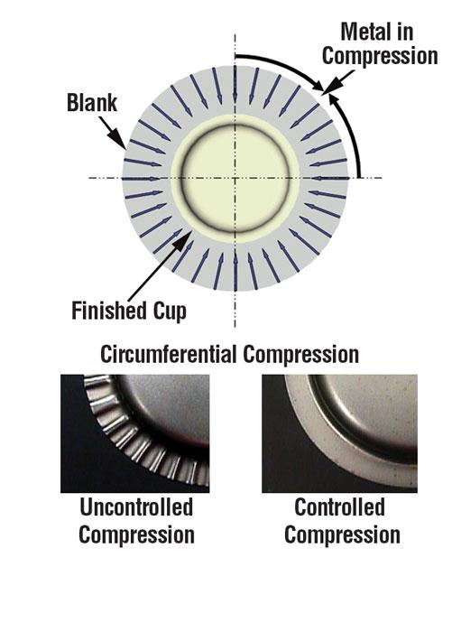
Figure 1
If compression is controlled by providing a space not much larger than the thickness of the metal between the die face and the drawing pad, the part will have a flat flange. If the metal is not controlled, the flange will be severely wrinkled.
For example, if you are making a part that requires a 10-in.-diameter blank made of 0.050-in.-thick metal, the chart shows that the first drawing percentage from blank to draw is 53 percent. This means the first draw punch must be at least 53 percent of the blank diameter, or a minimum diameter of 5.3 in. Using a drawing punch that is smaller in diameter than 5.3 in. could result in failure.
If the product diameter you are trying to achieve is smaller than 5.3 in., you will need a second drawing operation to convert the cup from 5.3 in. to a smaller diameter that is taller than the cup. The second drawing reduction percentage is 71 percent for 0.050-in.-thick material. Multiplying the diameter by 71 percent gives 3.763 in. as the minimum diameter of the second drawing punch.
If this diameter is larger than the product diameter, you need a third draw reduction. The chart shows this reduction as 74 percent, and 74 percent of 3.763 in. is 2.784 in.
This process repeats until you have reached a number equal to or smaller than your final part diameter. Note that after the fourth drawing station, it is common to keep the same draw reduction percentage as the fourth operation. Keep in mind that a draw reduction relies on keeping the surface area of the part the same for each drawing operation.
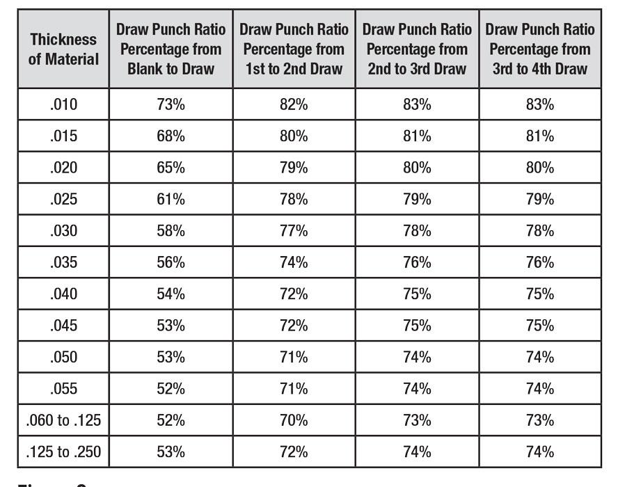
Figure 2
Use a draw reduction chart to determine the number and diameter of each of the drawing stations.


The Fabricator is North America's leading magazine for the metal forming and fabricating industry. The magazine delivers the news, technical articles, and case histories that enable fabricators to do their jobs more efficiently. The Fabricator has served the industry since 1970.
start your free subscription
Easily access valuable industry resources now with full access to the digital edition of The Fabricator.

Easily access valuable industry resources now with full access to the digital edition of The Welder.

Easily access valuable industry resources now with full access to the digital edition of The Tube and Pipe Journal.

Easily access valuable industry resources now with full access to the digital edition of The Fabricator en Español.
In this episode of The Fabricator Podcast, Caleb Chamberlain, co-founder and CEO of OSH Cut, discusses his company’s...


