


Manufacturing Engineering
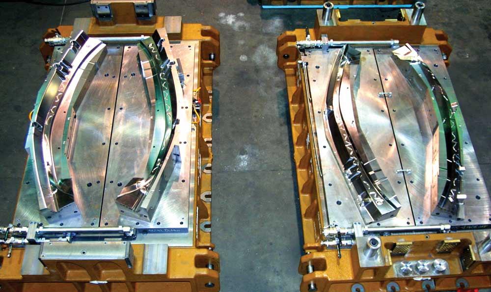
This is a cantrail (A pillar and roof side rail) hot stamp die, upper and lower, right and left.
As it is heated in a 900+-degree-C furnace, hot stamp blank material becomes very sticky, resulting in friction coefficients of 40 percent or more. Material coatings used to prevent decarburization and scale formation during blank heating can be very abrasive to tool surfaces. No lubricants can be used because of the ultrahigh temperatures. As a result, managing friction is critical to avoid excessive thinning, splitting, and cracking in the part, as well as excessive die wear from the abrasion.
Several methods are used to control friction. The part may be crash-formed without pressure pads when part geometry allows the free flow of material into the die cavity during forming. This is possible if there is not too much surface contact between the blank and die.
However, other methods are needed to control the part during forming to prevent its unintended lateral shifting, which would create the need for extra material addenda and post-forming trimming. Edge or pin gauges commonly are used to locate the blank during die loading. Stick pads may be used to grip or form the material in the center of the part. This is the opposite of most large cold stamping operations during which draw beads control material movement and ensure sufficient material stretch to remove loose metal and achieve a consistent form.
Because no lubrication is used and the material is very sticky, the primary forming challenges are friction-induced wrinkling of the material and keeping it hot enough to avoid hardening before the part is fully formed.
As soon as the heated material contacts the much colder die (typically below 200 degrees C), the heat starts transferring to the die, starting the rapid quench process. Consequently, forming should be done very quickly (usually in less than one second after the blank contacts the die) to ensure that the part remains pliable until it is fully formed. Minimizing the surface contact of the material being formed until the last part of the stroke will improve the process generally, and friction-caused thinning will be reduced.
While crash forming often will be the best die process, compression of flanges on the inside radii can cause wrinkling, with unacceptable distortion, or double metal after forming. In this case, a wrinkle control gapped pad is used to prevent excessive wrinkle height from forming. Nitrogen cylinders hold the pad apart to allow free metal flow into the cavity. These gap cylinders are compressed at the bottom of stroke to iron out the wrinkles before quenching.
To further complicate the situation, the blank expands when it is heated and the part shrinks after it cools off during quench. This makes it more difficult to gauge and control the part during forming, since gauging has to accommodate the shrinkage without losing effectiveness and allowing the part to move. That would be counterproductive to any attempts to use developed trim lines to reduce the cost of secondary laser cutting operations for trimming edges and cutting holes.
One of the more recent developments is hot piercing in form dies. After the part is fully formed at the bottom of stroke, holes are pierced before the part hardens. These holes can be used for finished part holes or they can be used as sacrificial manufacturing holes, often for locating the formed part in secondary laser cutting operations.
Hot trimming is also possible, and if it can eliminate laser trimming, it may be a viable strategy. However, both hot piercing and hot trimming are complex and are considered high-maintenance.
The quenching process rapidly cools the material. The temperature must drop at a rate in excess of 27 kelvins per second to change the austenitic microstructure into martensitic, without going through any ferritic or bainitic phases, which would prevent martensite formation. This requires sufficiently cool die surfaces (below 200 degrees C) that can absorb the heat from the part and transfer it to the water cooling channels that remove the heat from the die.
Hot stamp form and quench dies have specific requirements. The tool steel must be able to handle high temperatures and quick thermal changes, cooling chambers must be drilled, and higher-than-usual maintenance is needed.
The die surface heat transfer coefficient depends on contact pressure and surface roughness. It is important to achieve uniform contact pressure, even on side walls, and to keep the tool smooth and clean. It is also important to have sufficient press tonnage. When debris, such as a material coating, accumulates, the die must be cleaned or the contact pressure will drop quickly. That will slow down the quench process to the point where quench rates are too slow, resulting in soft spots caused by bainite formations.
The same contact pressure deterioration can result from tool surface abrasion (typically male radii) that causes slower quenching. This increases cycle time and part cost. It also can cause part distortion by quenching unevenly, leaving residual stresses from uneven part shrinkage. That can contribute to inconsistent geometry after laser cutting or assembly. Quench rates also depend on proper distance of cooling channels from the surface and on thermal conductivity of the tool steel at elevated temperatures.
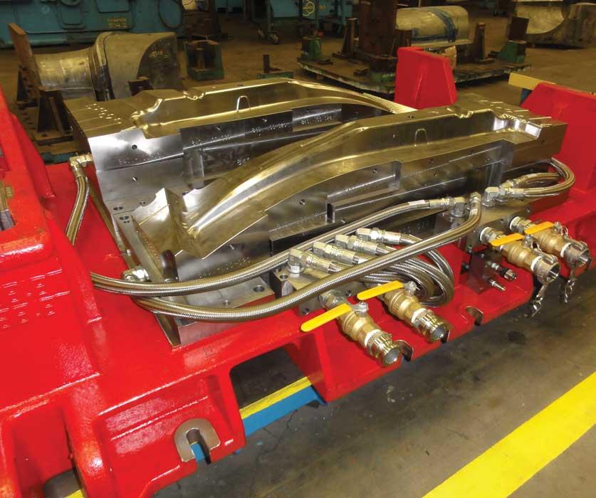
Last, the heat transfers into the water and is carried out of the tool. Water cooling typically occurs through drilled holes in the die. It is important to make sure that the water channels are matched to the facility’s water chiller capabilities (temperature, pressure, flow) so the tool uses all of the available chiller capacity to quench as quickly as possible.
It is also important to balance water flows between parallel cooling channels to maintain uniform quenching of the part, especially if the part geometry is sensitive to quench uniformity. Also, water flows must be turbulent to improve heat transfer capacity. High water pressure creates better cooling channel heat transfer coefficients and, therefore, more efficient heat transfer.
Thermographic cameras and infrared pyrometers are typical measuring instruments used to assess quench uniformity and quench rate, as well as part and die hot spots for process control. Changes in thermographic or pyrometric readings indicate problems that need to be resolved, such as clogged water lines, debris in the die, and worn tooling.
Temperature measurement instruments are also used to develop the thermal process windows for the part production. The windows are used for process control and documentation to determine how many seconds to quench, press tonnage, part leaving temperatures, and so forth.
Hot form and quench dies require more maintenance than conventional cold stamping dies because of the thermal expansion and contraction that takes place each press cycle. As the die heats up during quench, and then cools off during part unload, blank load, and part forming, heat checking occurs, which can cause tool cracks and water leaks. As a result, tool steels are generally H13 or better grade materials that can take the thermal shock as well as forming shock loads and abrasive materials.
Typically, water channels are cross-drilled into blocks that are assembled with O-ring seals. These tend to degrade over time and are replaced whenever tools are disassembled for maintenance and cleaning. Also, O-rings are exposed to heat damage between the surface and the water channel. Proper compression of O-rings is important to eliminate water leaks in the tools.
Tool steel cracks caused by thermal expansion, contraction, and heat checking usually occur between the surface and water channels. When excessive cracks are seen, a higher-quality H13 ESR variant tool steel may be warranted. Cracks can sometimes be repaired by welding.
When excessive die wear occurs, it may become necessary to replace the forming steels or to recut die surfaces. Water cooling channels make recutting more difficult, as it is important to maintain proper spacing from the die surface to maintain die strength and cracking resistance. Recuts generally are quite limited with hot form and quench tools, and they are difficult to achieve with deep-draw section side walls.
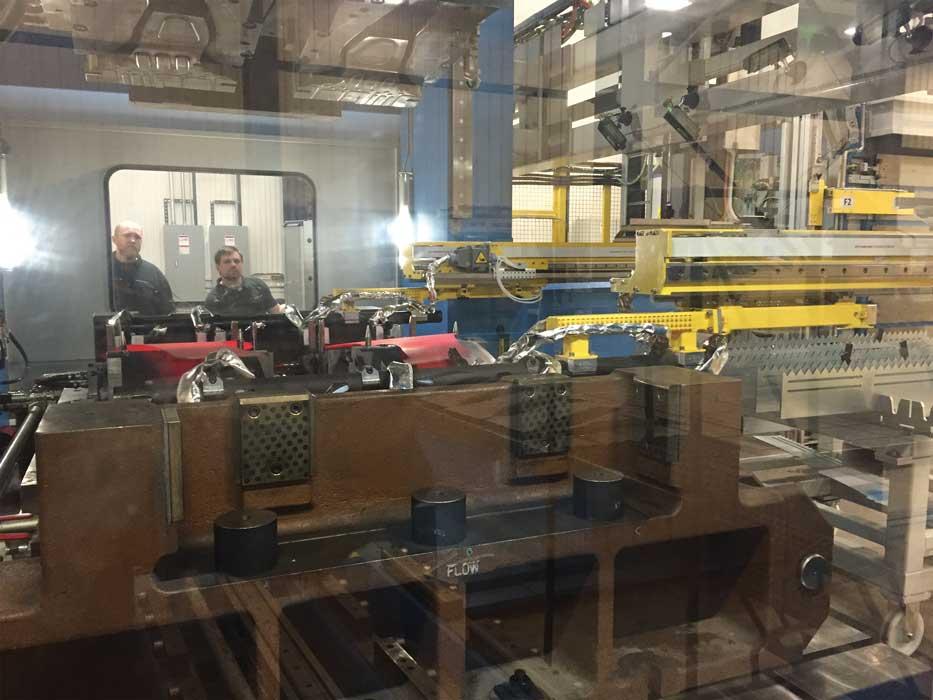
Right and left B pillars are being loaded and pulled down into pins that are gauging blanks off of their edges. The prebending helped maintain control of the part during forming and illustrates the softened state of the heated material.
Hot form and quench die tool steels must be replaced when they become too difficult to maintain. Replacement is complicated by the need for the new forming block to match mating sections of adjacent blocks. The adjacent die surfaces may no longer match original CAD models or scans of original dies, and the replacement detail has to be adjusted to match the adjacent, slightly worn blocks.
Significant damage will occur to the form and quench tool if it is double-hit by loading a blank onto a previously formed part that was dropped in the die while it was being unloaded. Side wall angles are often steep, and these become very effective wedges that tend to bend or break die steel sections. Although the die might survive, it may lose contact pressure on the side walls and consequently not properly quench without extra quench time and product cost. Automation units should be carefully tracking part flow to ensure that dies are unloaded properly and not double-hit. Redundant double-blank detection is highly warranted.
As with all stamping tools, product revisions may require the adjustment, or even replacement, of the tooling. With hot stamp form and quench dies, this can become more complicated since the tools are more difficult to machine and weld because of the through-hardened tool steel blocks and because they contain cooling channels.
When starting to build a hot stamp tool, it is important to assess the potential of product revisions and their nature. It may be possible to protect a tool to a limited degree (if there is uncertainty about the product design) by allowing extra material in localized areas of the die, and then removing the excess before going into production. Part of this assessment also should include deciding whether the part design can be made as currently designed, or if it will require some changes to radii or other features.
Formability simulations are important tools to use in the assessments. These can reduce risk so that a production tool can be made without having to build in provisions for minor changes. If simulations show risks, product changes can be made before the tooling is started. However, if there are questions about formability, or uncertainty about product design-driven potential revisions, it may make sense to produce low-cost physical prototype tools to prove out formability and assess product functionality in early vehicle builds.
Three levels of prototype tooling are available, typically. These are geometry only; geometry plus heat treating; and production-intent prototype for evaluation of developed trims and wrinkle/thinning control. Prototype tooling can be easily remachined or changed before launching the production tooling.Note
1. Automotive Industry Action Group CQI-9, Process Table 1, www.aiag.org/docs/default-source/product/cqi-9_3rd_processtablei_may2014.pdf?sfvrsn=0
Mike Austin is director, manufacturing engineering for Diversified Tooling Group Inc., 31240 Stephenson Highway, Madison Heights, MI 48071, 248-588-1100, maustin@diversifiedtoolinggroup.com, www.diversifiedtoolinggroup.com.
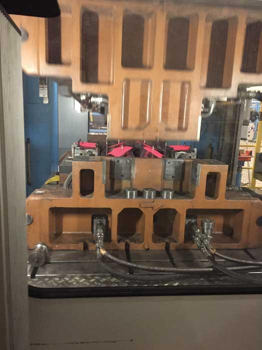
Six blanks yielded eight small hot stamped parts after laser cutting (two carsets per stroke). This shows pin gauging of tipped parts to aid formability.
Hot stamping, also known as press hardening or dry contact press hardening1, is a process used to form ultrahigh-strength steel (UHSS) into finished part shapes. The steel, commonly 22MnB5, is heated in an austenitizing furnace to 900+ degrees C, is formed, and then the formed part is quenched in the same forming die. The process of heating and quenching transforms the coarse austenitic grains to fine martensitic grains, thereby hardening the material to very high yield strengths—1,000 megapascal (MPa) and above.
The heating makes the material extremely soft and formable, much like a stick of chewing gum, enabling the forming of deep and complex shapes. Often this allows multiple parts to be formed as a single part.
The material’s softened state while it is heated allows the part to be formed readily to a final shape, and the quenching eliminates nearly all springback because residual stresses are relieved by the blank’s heating.
The hardening of the part is done after forming during the quench phase of the press cycle while it is stopped at the bottom of the stroke. A hydraulic or servo press must be used to allow the die to dwell there. Otherwise, it would be far too difficult to form the part without cracking it after the hardening stage.
After the part is quenched, it is removed from the form and quench die. The die cools off after having absorbed all the heat from the finished part and the die is reloaded with the next hot blank.
Typical press cycle rates are 10 to 30 seconds. Thicker material takes longer to run because of the extra time needed to quench.


The Fabricator is North America's leading magazine for the metal forming and fabricating industry. The magazine delivers the news, technical articles, and case histories that enable fabricators to do their jobs more efficiently. The Fabricator has served the industry since 1970.
start your free subscription
Easily access valuable industry resources now with full access to the digital edition of The Fabricator.

Easily access valuable industry resources now with full access to the digital edition of The Welder.

Easily access valuable industry resources now with full access to the digital edition of The Tube and Pipe Journal.

Easily access valuable industry resources now with full access to the digital edition of The Fabricator en Español.
In this episode of The Fabricator Podcast, Caleb Chamberlain, co-founder and CEO of OSH Cut, discusses his company’s...


