


Servo Press Scientist
Editor’s Note: Part I of this article, which appeared in the November/December 2017 issue of
STAMPING Journal®, reviewed the methods most commonly used to evaluate edge fracture in various materials.Edge fracture can be minimized by following certain steps. Following are the most important parameters that may reduce edge fracture after blanking.
Shaving, or two-stage blanking, improves the edge quality at the cost of an extra blanking step. Nevertheless, Volkswagen has successfully implemented it.
The first step is to trim away a smaller amount of material than what is finally required. The second step is to remove the remaining amount to create a smooth edge with improved accuracy (see Figure 1).
Tool wear is one of the most important parameters affecting blanked-edge quality. While it is impossible to completely prevent tool wear, it should be minimized as much as possible.
Figure 2 compares the effect of different levels of tool wear on the hole expansion ratio (HER). Factors such as punch/die clearance, blanking speed, blank material hardness, and tool coating affect tool wear.
Punch/Die Clearance. On one hand, when the punch/die clearance is too large, large burrs tend to form. These burrs will damage the tool, which subsequently may trim edges with bad quality, creating an edge that may fracture during flanging. On the other hand, very tight clearances, such as those observed in fineblanking, will lead to quick die wear as well.
Selection of the punch/die clearance depends on the blank material, so it can vary significantly. However, for advanced, high-strength steels (AHSS), a good starting point for cutting clearance is 10 to 20 percent. It is very important to pay attention to the uniformity of the clearance all along the cutting perimeter. Sometimes this uniformity is assumed and it is not carefully checked, which can lead to edge fracture during flanging.
Despite efforts to establish a uniform cutting clearance along the perimeter of the blanking tools, some misalignments or elastic tool and press deflections are inevitable, and these will affect the punch/die clearance once the process starts. These errors are more pronounced when blanking AHSS because of the higher forces used. A clear example of this situation is shown in Figure 3, where, for a nominal 10.3 percent clearance, the real values were between 4 and 15 percent.
One way to check the effective cutting clearance is to review the micrographs near the blanked edge. In addition, frontal pictures with a microscope can reveal rollover, shear, fracture, and burr along the edge.
Figure 1
In two-stage blanking, the first step (a) is to trim away a smaller amount of material than what is finally required. The second step (b) is to remove the remaining amount to create a smooth edge with improved accuracy (Gläsner et al, 2014).
Blanking Speed. Producing as many parts per minute as possible is always the objective. However, blanking at high speed can lead to certain undesired effects, such as tool and press vibrations. High reverse loading can damage the tools and the press in a long run.
A common solution is to use servo presses in blanking. They allow fast ram movement when there is no tool/blank contact, as well as reduced ram speed for a few millimeters during the blanking process.
Because of the tensile stresses present in mechanical blanking, microcracks generated at the cut edge act as stress raisers, accelerating the fracture in certain applications.
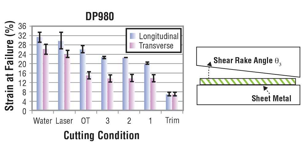
Cutting methods such as waterjet and laser can create edges with superior quality (see Figure 4), but these methods are relatively slow and thus not suitable for mass production. Because of their limited applications in blanking, waterjet and laser cutting are used mainly for prototyping.
The material should be trimmed along its rolling direction whenever possible. This allows for higher stretchability when processing AHSS.
During flanging of sheet metal, the higher tensile stresses tend to occur in the outer surface of the sheet—the surface not in contact with the punch.
Since the weakest part of a blanked edge is at the fracture zone, the burr should be placed facing the punch for flanging.
The strain distribution on the blank will change depending on the tool shape. The use of a conical punch can help to increase the HER of the material. The conical punch seems to delay the edge fracture, as compared to using a semispherical tool in flanging. The lowest reported HERs are obtained by using a flat-bottom punch.
Depending on the part, the use of regular flanging tool geometries may not be possible. In such cases, a large punch corner radius should be used if possible.
When the initial hole diameter is increased, the HER required to form the part is reduced, making it easier to achieve the desired final diameter without edge fracture.
Figure 2
The level of tool wear affects the hole expansion ratio (HER) (Gläsner et al, 2015).
While the final hole diameter is a concern, so is the height of the extrusion. The extrusion gets shorter as the initial hole diameter increases. Increasing the die corner radius will allow the extrusion to be higher before reaching a critical thinning value. But this modification depends entirely on the part design.
References
T. Gläsner, C. Sunderkötter A. Plath, W. Volk, H. Hoffmann, and R. Golle, “Methods to decrease cut edge sensitivity of high strength steels,” Key Engineering Materials, Vol. 611 (2014), pp. 1294-1307.
T. Gläsner, T. Schaffner, C. Sunderkötter, W. Volk, H. Hoffmann, and R. Golle, “Studies on the effect of tool wear on the production process in two stage shear cutting,” Key Engineering Materials, Vol. 651 (2015), pp. 1261-1270.
T. Gläsner, C. Sunderkötter, H. Hoffmann, W. Volk, and R. Golle, “Development of a 2-stage shear-cutting-process to reduce cut-edge-sensitivity of steels,” Journal of Physics: Conference Series, Vol. 896, No. 1 (2017), p. 012104.
P. Larour, J. Freudenthaler, R. Eßbichl, M. Kerschbaum, H. Horinek, and L. Samek, “Influence of shear cut edge condition on conical hole expansion ratio,” presented at the SCT 2017, Amsterdam, June 2017.
H.C. Shih, C.K. Hsiung, and B. Wendt, “Optimal production trimming process for AHSS sheared edge stretchability improvement,” SAE technical paper No. 2017-01-0994, 2014.

Professor Emeritus and Director - Center for Precision Forming


The Fabricator is North America's leading magazine for the metal forming and fabricating industry. The magazine delivers the news, technical articles, and case histories that enable fabricators to do their jobs more efficiently. The Fabricator has served the industry since 1970.
start your free subscription
Easily access valuable industry resources now with full access to the digital edition of The Fabricator.

Easily access valuable industry resources now with full access to the digital edition of The Welder.

Easily access valuable industry resources now with full access to the digital edition of The Tube and Pipe Journal.

Easily access valuable industry resources now with full access to the digital edition of The Fabricator en Español.
In this episode of The Fabricator Podcast, Caleb Chamberlain, co-founder and CEO of OSH Cut, discusses his company’s...


