


R&D Manager
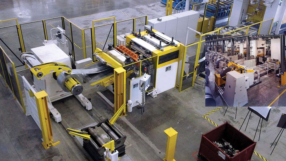
In a nonautomated feed system line, making manual adjustments to the press feed can take significant time because an operator must walk back and forth to each side of the line. Automated feed equipment sharply reduces downtime that occurs during changeovers. A spectrum of feed line automation is available, from adding hand cranks for single-point adjustment to full-blown automation that simply requires an operator to hit the recipe and a “Go” button. Here, even the threading is automated.
The increased reliability and speed of servo feeders has made them commonplace in today’s pressroom. Servo-feed technology can enhance part quality and extend tool life while operating at higher speeds than air feeds.
In addition, a servo feed’s flexibility expands the types of materials that a stamping manufacturer can process.
Although a servo feed costs more than an air feed, a servo feed with automated functions can deliver a quicker return on investment (ROI) than a no-frills machine because it reduces downtime with every changeover. With every job switch, multiple adjustments need to be made to the press feeding equipment that add up.
Some typical pressroom scenarios illustrate why it is wise to look beyond the basic machine to a modern servo feeder.
Each job may require a servo-feed height adjustment to account for varying passline die heights. Material should not feed uphill or downhill, but as close to level as possible.
Many press-mounted servo feeds are adjusted via slotted plates bolted directly to the press. To perform a passline height adjustment this way, first, the weight of the servo feed must be supported and then the mounting bolts must be loosened. Only then can the passline height be adjusted manually. The mounting bolts must then be retightened.
Basic cabinet-mounted feeds are equipped with slotted press mounts with locking bolts on both the front and back sides of the feed. These bolts require a wrench to unlock and lock the mounts for the height adjustment. Hopefully that wrench is where it is supposed to be when the time comes to make adjustments. If it is not there, a search party must be assembled to find it, because setup cannot be completed without it. Once the wrench is located, the operator, with wrench in hand, loosens the front locking bolts. Often, loosening the back locking bolts requires walking all the way around the feed line—and sometimes even the press—to do so. Then the operator has to walk back to the front of the line to make the actual passline height adjustment. Doing so often requires various additional tools. To tighten the back press bolts, the operator reverses the process, meaning another stroll around the press or feed line until the process is completed. Finally, the tools are put away.
If exit automation, conveyors, or other equipment are in the way of the exit, that involves a long walk, maybe with a cup of coffee and a chat along the way for good measure. And the operator must remember to bring the wrench to lock the press mounts each time to avoid making extra laps.
A simple investment that pays off big in terms of time savings is a tools-free press mount (see Figure 1). This assembly is attached to the feed, which then attaches securely to the press, making vertical adjustments possible without the use of tools or laps around the press and feed line. Now operators can adjust the passline height with a hydraulic or screw jack using a permanently attached handle. To raise the feed, they turn it one way. To lower it, they turn it the other way. There is no walking back and forth, removing or reinserting the handle, and storing the handle when not in use.
For additional efficiency, this function can be motorized. Push buttons move the feeder up or down until it is at the desired height. This is much easier than finding wrenches; unlocking press mounts; and finding, turning, and removing and reinserting handles. In addition, an encoder can be added to monitor the position information for a job recipe, enabling the feed to automatically move to the right height for each stored job.
Mechanical roll stop adjustments help optimize pilot release timing and pre vent the stock from pulling backward during feed roll (pilot) release. Basic adjustment mechanisms comprise two individual screws located on top of the machine on opposite sides. The operator uses two wrenches or an adjustable spanner wrench to make adjustments. Again, the tool must be located, and sometimes it’s not where it’s supposed to be.
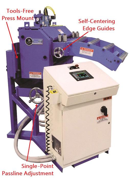
Figure 1
with single-point passline adjustment and self-centering edge guides can pay off quickly in reduced setup time.
Next, the operator must climb a ladder to get on top of the machine, thread the material, and close the roll on it. He or she uses the tool to break jam nuts loose and adjust the screw, cranking it down until it bottoms out, then back it off a half-turn, lock the jam nut, climb back down, then carry the tool and ladder to the back side of the line. Then the operator must climb back on top of the machine and loosen that jam nut, run it down, back it off half a turn, lock the jam nut, climb back down, and then come back around carrying both the tool and the ladder. Whew!
To make matters even worse, it’s likely that the roll gap is left unadjusted in a worst-case position because the adjustment process is so inconvenient. This extended travel can cause inaccurate feed length, premature wear on the pivot assembly, slow pilot timing, and, ultimately, reduced productivity.
An investment in a single-point roll stop adjustment would change this operation to a single hand-crank on the operator’s side of the equipment. The operator could release the shaft brake with a quarter-turn of a handle, rotate the hand-wheel until it bottoms out against the material, back it off a half-turn, and lock the brake. Done. Now, a hazardous task that could take 15 minutes can be accomplished in 30 seconds.
To adjust the material width on machines with base-model edge guides, the operators have to loosen and readjust manually a sliding roll assembly on each side of the line. On larger lines that they cannot reach across to adjust, more back-and-forth activity is required. If the machine is not equipped with scales, aligning the material to the centerline is even more challenging. Maintaining the centerline during width adjustment is critical to an efficient and consistent operation. If this measurement is off, the material goes through the feed rolls at an angle, causing the material to track off-center. This brings bad results or lost time to troubleshooting and correction.
A simple approach to preventing this is using hand-crank edge guides with self-centering and independent adjustments. This approach voids most of the variability and inconsistency. Adjusting the front and back guides using a single hand wheel on the operator side eliminates the need to walk around the back side of the feed line to adjust. Being able to offset the guide centerline using the same hand wheel compensates for misalignment and die position, and coil placement variation. Motorizing this function allows push-button control. Adding an encoder allows a position-stored job recipe to facilitate the operation automatically.
Each individual manual adjustment doesn’t appear to take a lot of time, but collectively, they may slow changeover time significantly.
Press feed setups cannot be done while the press is running, so the time required to make these adjustments is very costly.
Imagine a stamper has tools-free press mounts, but all other operations are adjusted manually with tools instead of hand cranks or motors. Let’s say all these adjustments add up to, conservatively, 15 minutes of setup time per changeover. At a press rate of $2,000/hour, two changeovers per day, 30 minutes total equals $1,000 in lost time in just one workday. That adds up to $5,000 per single-shift week, and $260,000 over a year. Facilities running two or three shifts would realize double or triple that amount.
If the process were automated with auto-positioning encoded controls, the setup recipe would be stored so that the operator would simply push a button to go. That would require only a fraction of the time needed for manual adjustments and could easily cut $250,000 in lost press time per shift each year. An investment in automated functions costs much less, typically.
Servo-Piloting. Servo feeds equipped with an air-operated pilot release mechanism have limited speed capability. Servo feeds equipped with a servo-driven pilot release provide programmability and can achieve very high speeds (see Figure 2). A servo-piloting feed’s response time is 5 milliseconds (ms) compared to a pneumatic piloting system’s 50 to 150 ms. In addition, a servo-piloting system provides energy savings and requires less maintenance because compressed air requirements are lower.
Tailout Feeds. If material savings and improved safety are desired, a tailout feed can help (see Figure 3). These feeds, positioned downstream of the servo feed, can reduce space between the feed and die. During die changes, the tailout feeder retracts for added clearance.
But when the line is running, it telescopes out close to the die. In addition to reducing waste, it leaves less material in the die, making material removal quicker and safer.
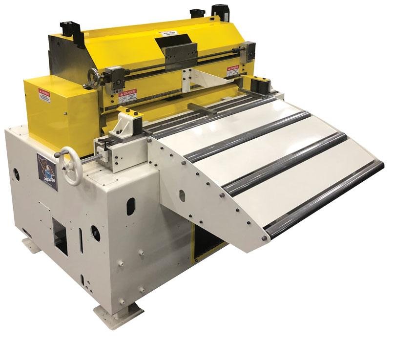
Figure 2
Especially well-suited for high-production environments, servo-piloted feeds are completely programmable and have a 10 to 30 times faster response rate than air-piloted feeds.
Setup Software. Some OEMs’ software helps takes the guesswork out of setting up a servo feed. Finding an optimal feed velocity and acceleration, typically accomplished through trial and error, is calculated automatically based on the desired press speed and feed window. Operators can enter their feed window parameters in degrees and press speed into the controls, and the software calculates the recommended acceleration and maximum velocity
settings.Don’t be penny wise and pound foolish when buying pressroom equipment. Investing in motorized or automated functions can net a good ROI. Although it’s better to make the investment upfront with new equipment, it’s never too late to improve the process. Many of these features can be added to an existing system.
Bruce Grant is R&D manager and John Kwiatkowski is marketing manager for COE Press Equipment, 40549 Brentwood Drive, Sterling Heights, MI 48310, beg@cpec.com, jmk@cpec.com, www.cpec.com.
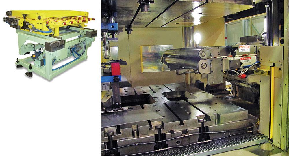
Figure 3
The tailout feed telescopes close to the die when the line is running but retracts during die change for added clearance. This option leaves less material in the die to reduce waste and makes material removal quicker and safer.


The Fabricator is North America's leading magazine for the metal forming and fabricating industry. The magazine delivers the news, technical articles, and case histories that enable fabricators to do their jobs more efficiently. The Fabricator has served the industry since 1970.
start your free subscription
Easily access valuable industry resources now with full access to the digital edition of The Fabricator.

Easily access valuable industry resources now with full access to the digital edition of The Welder.

Easily access valuable industry resources now with full access to the digital edition of The Tube and Pipe Journal.

Easily access valuable industry resources now with full access to the digital edition of The Fabricator en Español.
In this episode of The Fabricator Podcast, Caleb Chamberlain, co-founder and CEO of OSH Cut, discusses his company’s...


