Sales Manager, Hydroforming
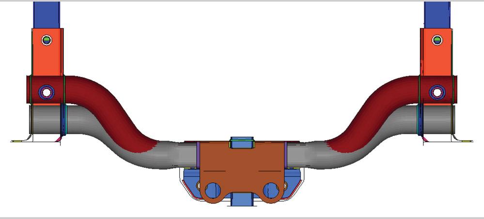
To keep the cycle time for the new trailer hitch as short as possible, the design called for less severe bending (gray tube) than the original (maroon tube). These bends were accomplished by the closing action of the hydroforming die, eliminating a separate bending step.
Automotive veterans with more than a couple of decades of experience likely remember the wave of hydroforming that swept over the industry in the 1990s.
Because hydroformed assemblies often have fewer parts, less weight, and more strength than conventional assemblies of stamped components, hydroforming earned a spot at the forefront of automotive manufacturing technology—a position it holds to this day. Reducing the weight and increasing the strength help automakers meet fuel efficiency and safety targets, while reducing the overall part count helps offset the slower cycle time of a hydroforming press (compared to a stamping press).
While stamped-and-welded assemblies continue to have a strong presence in automobile design, many such assemblies were substituted with assemblies based on hydroformed tubes in recent decades. Sometime in the late 1990s or early 2000s, the role of hydroforming shifted; no longer a substitute method for conventional processes, it became a primary manufacturing process. In other words, assemblies were being developed, from scratch, to be hydroformed.
While much of the activity started at the front end—radiator supports, engine cradles, and suspension components—it didn’t stop there. A recently developed trailer hitch, which also serves as an integral part of a frame for a full-size pickup truck, has rounded out the technology’s appeal, running nearly from bumper to bumper.
Trailer hitches commonly used on passenger cars and SUVs start at Class I—usually made from square tube that measures 1.25 by 1.25 inches—for towing up to 2,000 pounds. They go up to Class III, made from 2-in. square tube, for towing up to 6,000 lbs. Class I, II, and III trailers typically carry a motorcycle, snowmobile, four-wheeler, or a small boat. Tongue weights are 200 to 600 lbs.
For higher classifications—Class IV, V, Xtra Duty, and Commercial Duty—the trailer weight is 10,000 to 20,000 lbs., and the tongue weights are 1,000 to 2,700 lbs.
Of course, nothing is that simple. Making a trailer hitch robust and safe enough to meet the relevant specifications means meeting a handful of additional criteria: Weight-carrying hitch force and weight-distributing hitch force come into play, measured in terms of downward compressive and tensile forces and left- and rightward forces. Another critical characteristic concerns the load location. Although the protruding end (the ball mount) and the ball are the focus, the development process can’t overlook the strength needed at the chain attachment locations. Also, a hitch often is subjected to additional tensile forces, such as when a trailer has slid off of the roadway and ended up in a ditch. Pulling a trailer out of a ditch puts far more stress on the trailer hitch than merely towing the trailer on a roadway. For this project, the original equipment manufacturer (OEM) specified that the hitch would have to withstand a tension force up to two times the trailer’s weight at 20 degrees off-center to the left and to the right. As an integral part of the vehicle’s frame, this hydroformed assembly would be subject to all the standard OEM testing requirements.
In this case, the OEM already had a trailer hitch made on a CNC tube bender. To win the contract, the hydroformed part would have be just as strong yet lower in weight than the bent part. The OEM mandated that the hydroforming process would result in zero engineered scrap and, of course, hydroforming would have to compete on cycle time as well.
Although CNC bending is well-known for its accuracy, in terms of dimensions and tolerances, its accuracy relies on many factors, including proper tooling setup, proper lubrication, consistent tube characteristics and seam location, and programming. Even when all goes well and the first parts are made accurately, tool wear can cause accuracy to drift somewhat over time, so its repeatability isn’t guaranteed. This doesn’t mean that CNC bending is a shoddy or unreliable process. Far from it; all things considered, it can be daunting process to compete against. That said, hydroforming uses water under tremendous pressure to force a tube to conform to a die, so hydroforming is almost impossible to beat for dimensional accuracy and process repeatability.
Cycle time requires close attention. CNC bending is limited to one bend at a time and one part at a time, and the part must undergo additional processing steps, thereby adding both time and cost. Although hydroforming isn’t known for dazzling cycle times—it takes a while to load a tube, bring the two die halves together, seal the tube ends, pump the tube full of water, and build enough pressure to form the tube—the process can get an edge by forming several tubes simultaneously in each press stroke. Overlapping two stages of the process—for example, beginning to fill the tube with water as the die is closing—also cuts down on cycle time.
Hydroforming has another trick up its sleeve: Work hardening. While every cold-forming process imparts at least a small amount of work hardening, strengthening the workpiece in the forming regions, hydroforming can perform a small manufacturing miracle. When the tube’s diameter is smaller than the die cavity along the tube’s entire length, pressurizing the tube from the inside and increasing its diameter to fill the die cavity improves the tube’s strength along its entire length. This means that, when shooting for a specific strength target, hydroforming can use a thinner-walled tube than other manufacturing processes, which reduces part cost and weight. Reducing part cost is music to any manufacturer’s ears, as is reducing part weight. In automotive applications, reducing weight is more than just a benefit. It’s part of a mandate as automakers seek to improve fuel efficiency to comply with the corporate average fuel economy standard.
Hydroforming has one more benefit. Although the initial tube feedstock is round, hydroforming can impart a variety of shaped features and unusual contours, including flat areas and nonround sections, to accommodate the installation.
In many cases, engineers design a part; in others, they design the process needed to manufacture the part. In this case, it was both. Because the part already existed and the OEM had somewhat aggressive improvements in mind, this wouldn’t be easy to accomplish. The part already had been through at least two generations, so any slack in the original design previously had been tightened up.
Challenges included a mass reduction of 40 percent (30 lbs.) from the baseline concept and a mass reduction of 14.8 lbs. compared to the previous-generation hitch. Second, the OEM wanted zero engineered scrap. In many cases, a manufacturing process includes a little extra material that later is trimmed off.
Sometimes a little extra material is helpful, for example allowing additional grip length for bending, but this consumes extra material and extra time (in the subsequent trimming operation). Finally, the OEM wanted the process to produce two hitches, one in Class III and one in Class IV; the Class IV hitch would require a 40 percent towing capacity improvement, an increase from 10,000 to 14,000 lbs.
Part Development. The original hitch design had four bends. Most of the tube was a straight length; the receiver was attached in this location at the center of the hitch. The four bends brought the tube ends to the proper locations so they could be attached to, and become a part of, the vehicle’s frame.
The hydroformed hitch design had a similar shape, but the bends were less severe. The intention of the design was to do all the forming in the hydroforming die. In many cases, tubular parts are bent on a bender before hydroforming, but relying on the die’s closing action to bend the tube removes a forming operation and a material handling step.
However, changing the shape of the hitch meant more development work was necessary. Reducing the bend angles changed the locations at which the hitch would join the frame, making it necessary to evaluate how the new design would fit into the existing space. How the hitch would be joined to the frame, specifically in the bolt hole sizes and locations, also had to be evaluated.
When the part development stage was completed, a finite element analysis (FEA) simulation determined the initial cut of the die cavity, taking into account all of the necessary process parameters and the amount of springback. A full FEA on both the hydroformed tube and the entire hitch assembly aided the design process and played a large role in optimizing the product’s strength and mass reduction.
Two critical criteria concerned wall thickness and material hardness, parameters that change during the forming process. Bending a tube causes material to stretch and thin along the outboard areas of the bend, which was a concern. Therefore, the analysis was used to determine the maximum bend angles so that wall thinning was kept to an acceptable level.
FEA also was used to verify that the tube would be able to fill out the die cavity for appropriate dimensioning. The material would work-harden as the internal pressure would force it to flow into the various contours and recesses of the die cavity. If it hardened too much before the forming process was finished, the risk was that the hydroforming pressure wouldn’t overcome the material’s increasing strength, resulting in an underformed part.
Prototyping. The first prototyping stage concerned the part shape. The initial parts were measured thoroughly to determine if the die was satisfactory from the start or if adjustments were required to achieve the desired shape. At this stage, the tube was longer than necessary—which was intentional—and it was trimmed to size after the part was hydroformed.
The dimensional evaluation determined that the die produced accurate parts, so the second prototyping stage involved part length adjustment. The raw tube length was reduced, based on known measurements, to arrive at the necessary length.
The result was a dimensionally satisfactory part.
In the end, the new hitch design met the criteria as described in Society of Automotive Engineers standard SAE J684, and it met the OEM’s requirements. A hardness measurement taken after the tube was hydroformed revealed that indeed the work hardening had helped, as intended, adding 10,000 pounds per square inch to the trailer hitch’s strength.
Certainly towing systems have been used since the dawn of the automotive age, whether for recreation or a vocation, greatly increasing the utility of the vehicle. Even a small trailer can triple or quadruple a vehicle’s payload, or allow its user to enjoy an afternoon of sailing or a week of camping.
This project was another step forward in trailer hitch design, providing a smaller, lighter, and more capable hitch than the previous generation.
Jonathan Ball is sales manager, hydroforming, for Schuler Inc., 7145 Commerce Blvd., Canton, MI 48187, 734-207-7243, www.schulergroup.com.


The Tube and Pipe Journal became the first magazine dedicated to serving the metal tube and pipe industry in 1990. Today, it remains the only North American publication devoted to this industry, and it has become the most trusted source of information for tube and pipe professionals.
start your free subscription
Easily access valuable industry resources now with full access to the digital edition of The Fabricator.

Easily access valuable industry resources now with full access to the digital edition of The Welder.

Easily access valuable industry resources now with full access to the digital edition of The Tube and Pipe Journal.

Easily access valuable industry resources now with full access to the digital edition of The Fabricator en Español.
In this episode of The Fabricator Podcast, Caleb Chamberlain, co-founder and CEO of OSH Cut, discusses his company’s...