


Executive Sales Manager
Millions of miles of pipelines will be built in the coming decades, both in replacement and new construction. Most of the available pipelines around the world will reach replacement age if they haven’t gotten there already, and the world needs additional pipelines, too. These projects will require countless welds.
Furthermore, essentially every branch of industry has embraced welding, and many have been using welding in metal assembly work for almost 100 years. Techniques and materials are improved every year in the search for increasing efficiency, and the growing skill of many welders has raised this industrial process to an art form. However, in welding, an attractive appearance can hide a defective weld. This concerns not just the welding process, but weld preparation steps.
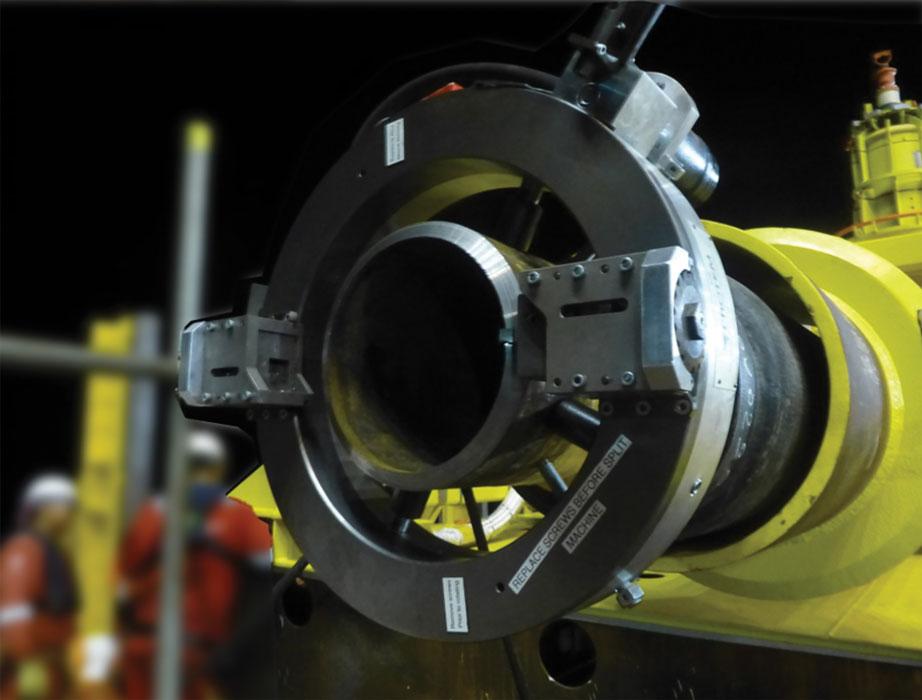
Despite using welding stations on the cutting edge of technology, the stage prior to welding, weld preparation, often is neglected or is performed with inappropriate techniques. The materials must be properly dimensioned and cleaned (see Figure 1). Otherwise, the result is likely to be a poor-quality weld, even though the weld might look good on the surface.
Cracking is one of the most common defects in welding. It is caused by excessive mechanical stress in the weld bead. The most common types of cracking are hot and cold cracking.
The design of the weld assembly, specifically the bevel land width, is one of the factors that increases the likelihood of hot cracking. As its name implies, this type of cracking occurs when the metal is still hot and in the process of solidifying. As the bevel land width decreases, the mechanical stress that results from the metal solidifying increases. If this stress is too high, cracking occurs during the change in phase.
Cold cracks appear after welding (immediately, several hours later, or even several days later). This defect type is caused by a simultaneous combination of three factors: a temper structure that is hard and fragile, residual mechanical stress (related to clamping, for example), and the presence of diffusible hydrogen in the weld bead. The last factor may be related to poor edge preparation. When a rusty or poorly degreased part is welded, the hydrogen present in the rust or the hydrocarbons in the grease decomposes in the weld. Stresses then appear when the metal is cooling down. Although the stresses are small, as the concentration of stresses increases, so does the likelihood of a crack.
When accompanied by other precautions such as drying the electrodes in ovens or preheating parts to be welded, dry machining the joint edges—that is, without a coolant—reduces or eliminates the presence of hydrogen, reducing the probability of cold cracking.
Lack of fusion is poor adhesion of the weld bead to the base metal, the result of an unmolten contact area. One cause is improper bevel land thickness. A bevel land that is too thin relative to the electrode diameter is likely to disturb the arc, causing it to lean toward one of the walls. As a result, fusion occurs on one of the edges and the bevel fills with molten metal, but fusion is incomplete or lacking on the other edge.
Because the arc has reached the root directly and the other side of the bevel, the zones in question are not melted but merely covered by a layer of filler metal. The weld may appear to be good, but in fact it doesn’t have the metallurgical continuity it needs for a structurally strong joint. Because these defects usually are located inside the welded joint, a visual inspection is unlikely to detect them. Finding them requires inspection techniques such as ultrasound or radiography.
Similarly, a bevel land thickness that is incompatible with the welding parameters can lead to incomplete or excess penetration. Incomplete penetration often is characterized by an unmelted zone at the root of the weld; excessive penetration causes a surplus of molten metal at the base of the welded joint. These two defects are caused by improper welding parameters (current, voltage, or welding speed) and dimensions—improper clearances between the parts or poorly controlled land thickness.
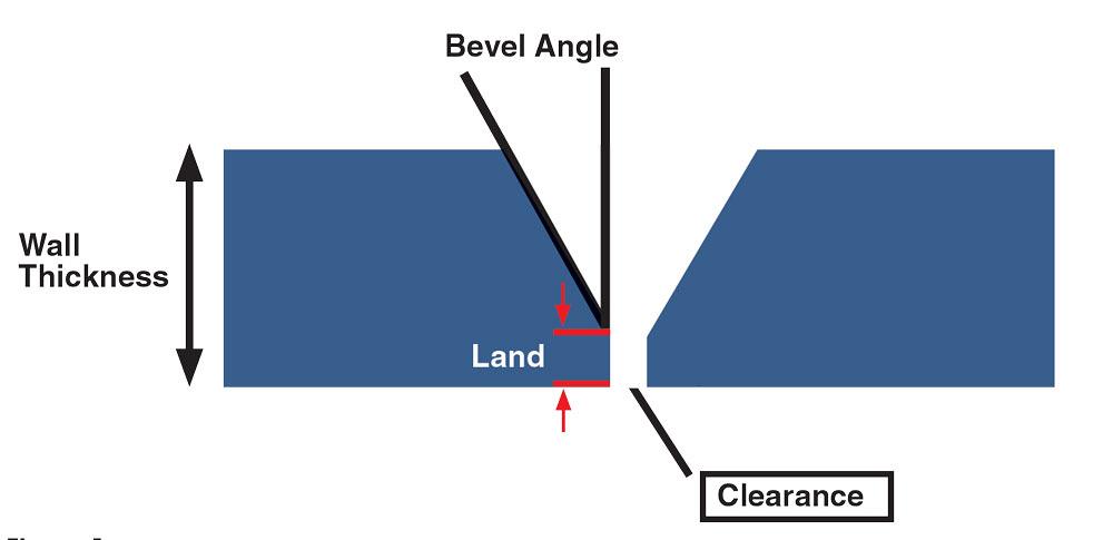
Figure 1
A closeup of a tube or pipe weld joint shows the three main dimensions of a joint: wall thickness, bevel angle, and land. A strong joint depends on proper joint design, preparation, and weld procedures. Often the middle step, weld prep, doesn’t get enough attention, resulting in substandard welds.
Insufficient clearance leads to incomplete penetration. When the distance between the parts is too small, molten material doesn’t flow into the gap. On the other hand, too much clearance allows too much molten metal to flow into the gap and protrude into the tube or pipe’s inside diameter (ID).
In certain cases, these defects can be eliminated by highly accurate positioning. If the parts to be welded are not perfectly parallel, unequal clearance between the parts gives rise to localized points with excess or incomplete welding. Accurate facing is critical.
Proper land thickness also is critical for proper penetration. For example, if the welding parameters call for a land 1.5 millimeters thick, using a land that is too thin (perhaps 0.5 mm) results in excessive penetration, whereas a land that is 2.5 mm thick will lead to incomplete penetration.
Bevel land consistency also is critical (see Figure 2). If the pipe is out of round, using an automated beveler creates a consistent bevel on the outside diameter, but the ID needs a corresponding process—counterboring—to make the ID round. This ensures a land that is consistent around the entire circumference.
Foreign matter in many forms can lead to weld contamination and result in a substandard joint.
Blowholes. A poorly prepared surface can cause blowholes to appear in the weld. The presence of water, rust, or grease leads to the formation of gas bubbles liable to be trapped inside the bead. As is the case in cold cracking, dry machining reduces the probability of this defect.Corrosion. Stainless steels, aluminum alloys, and other metals that aren’t prone to corrosion are at risk of iron contamination, which can lead to corrosion. The problem is galvanic corrosion, which occurs when iron particles are in contact with an electricity-conducting medium, such as damp air. Galvanic corrosion causes the passive layer of stainless steel to deteriorate progressively, which often leads to pitting. It likewise can leave unsightly rust spots on other alloys.
Iron particle contamination often comes from using equipment for carbon steel and other metals. Keeping tools separate is a good shop practice, so anything that contacts a stainless steel workpiece—clamps, vises, saw blades, machining tooling, grinding wheels, and deburring brushes—must be used for stainless steel only. Using such tools for both carbon steel and stainless steel results in contaminated stainless steel.
In some cases, direct contact isn’t necessary. Carbon steel particles can become airborne, so carrying out machining or grinding operations on carbon steel near another metal can be enough to lead to cross-contamination.
When cutting is carried out by a thermal process, such as oxyfuel, plasma, or laser, the cut quality may prove to be satisfactory when made by an experienced operator or with the help of an automated system. However, in most cases, these techniques create a heat-affected zone (HAZ) close to the cutting point. Significant heat input changes the material’s physical characteristics, which causes significant changes in a weld’s strength. The area in question requires another step, machining, to eliminate the HAZ.
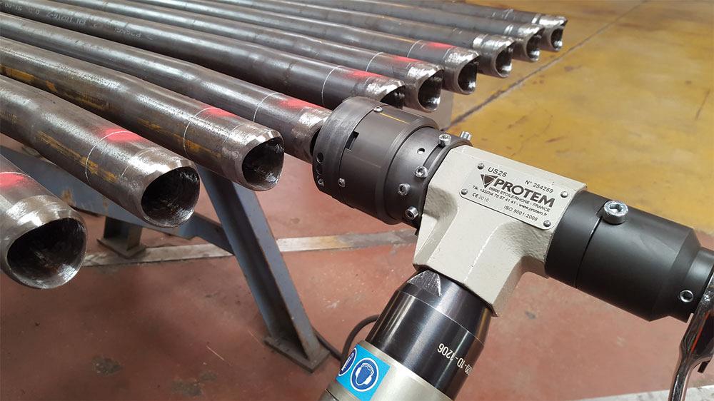
Figure 2
Using a tool designed for a specific purpose—in this case, for beveling saddles—helps to ensure consistency in bevel angles and
dimensions, which assists in making welds that are robust and durable.
While good weld preparation contributes to the quality of every weld, joining materials with a high-density energy source—laser or electron beam—highlights just how critical weld preparation is. These processes use a beam aimed accurately and focused tightly. The ratio of bead width to penetration depth can be extreme, rarely more than 5 mm wide and often several hundred millimeters deep, for a joint welded in a single pass. Assemblies welded in this way do not require bevels, but they do need extremely accurate facing. For example, preparation for laser welding is acceptable if the misalignment is less than 0.01 mm.
Moreover, parts must be free of any contamination, especially electron beam welding. Because electron beam welding operations are carried out in a vacuum, the workpiece must be thoroughly degreased and dry. Water and hydrocarbon residues interfere with the process of establishing a vacuum.
Even common welding processes, such as gas tungsten arc welding or gas metal arc welding, need extra attention in the preparation step when the welds are carried out by automated processes, such as orbital or robotic welding. An experienced welder can make adjustments to compensate for alignment defects and slight variations in the bevel or land, but an automated system doesn’t have this capability.
Welding is always a delicate operation. Many parameters have to be known and mastered for obtaining the best possible results; any factor that isn’t optimal is likely to cause a defect. Despite upgrading techniques and expanding knowledge on the subject, nonconforming weld joints continue to plague the industries that rely on welded tube and pipe assemblies. The consequences of a poor weld can be disastrous in both schedules and budgets. Repairing a welding bead can take several hours or even several days in the case of a major assembly.
This highlights the importance of designing the weldment correctly and the importance of accurate and consistent machining of bevels and lands, and counterbores when they are necessary. Automated processes, whether done with a machine or a hand tool designed for the specific purpose, are necessary for achieving the necessary dimensional accuracy and consistency.
Whether using a beveler on straight-cut ends or saddles, using a facing process to create a land, or using an ID machining tool to create a counterbore, the tools and machines designated for these tasks provide the accuracy and consistency that meet or exceed modern fabrication norms. It’s a matter of learning about all of the tools and machines that are available and ensuring that the operators are trained in their use.
Good shop practices also are required. Knowing when to use a coolant or a lubricant, and when not to, is just as important as separating the tools and work areas used for carbon steel from stainless steel.
Nadia Reicher is executive sales manager for Protem USA LLC, 29340 Industrial Way, Ste. 402, Evergreen, CO 80439, 303-955-4862, www.protemusa.com.


The Tube and Pipe Journal became the first magazine dedicated to serving the metal tube and pipe industry in 1990. Today, it remains the only North American publication devoted to this industry, and it has become the most trusted source of information for tube and pipe professionals.
start your free subscription
Easily access valuable industry resources now with full access to the digital edition of The Fabricator.

Easily access valuable industry resources now with full access to the digital edition of The Welder.

Easily access valuable industry resources now with full access to the digital edition of The Tube and Pipe Journal.

Easily access valuable industry resources now with full access to the digital edition of The Fabricator en Español.
In this episode of The Fabricator Podcast, Caleb Chamberlain, co-founder and CEO of OSH Cut, discusses his company’s...


