


Cold drawing principles
One process, five discrete steps

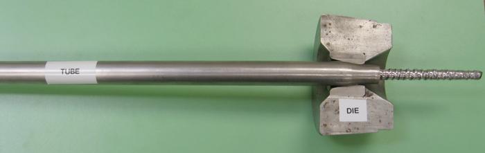
Figure 1: Rod drawing uses a die to determine the tube’s OD and a rod to determine the tube’s ID.
Drawing a tube from one size to another sounds simple. The process has two main steps: crushing one end (also known as pointing the tube), then drawing it through a die that has the correct ID. When the process is finished, the tube’s OD matches the die’s ID.
In reality, it’s much more complicated than that. A successful draw is a product of five distinct steps:
- Procuring the raw material
- Preparing it for drawing
- Drawing
- Straightening
- Finishing and final inspection
Tubing for redrawing can be either welded or seamless. The redrawing process for each is essentially the same; therefore, processes described in this article apply to both.
Welded tubing is produced from strip that has been rolled, slit, and coiled. After the coil is delivered to the tube production facility, it is uncoiled and fed into a mill that forms it into a tubular shape and the resultant seam is welded. Carbon and low-alloy steels usually are electric resistance welded (ERW), whereas stainless steels are gas tungsten arc welded (GTAW).
Seamless tubing may originate from pierced tubing (carbon or low-alloy steel) or extrusions (stainless, high-alloy steels, and nickel-based alloys). They may be further processed by pilgering or reducing. Another raw material is a drilled bar, which usually is used for special alloys or tolerances.
While the equipment and procedures discussed here may be applicable to most alloys, they are aimed primarily at carbon and low-alloy steel, stainless steel, and nickel-based alloys. Copper and aluminum usually are produced by high-volume processes, while titanium and zirconium alloys are better suited to low-volume, specialized processes such as pilgering and tube rolling.
1. Procurement
Drawing begins with procuring the raw material. The purchase order should specify the material’s chemistry and dimensions including tolerances—size, wall thickness, concentricity, and straightness. In most cases, the annealed properties are specified for maximum softness. These requirements may be included in a proprietary specification or an ASTM, AMS, or MIL code or specification.
2. Pointing
The next step is pointing, which is the process of decreasing the diameter of several inches of material at the tube’s end so it can enter the drawing die. The three most common methods for pointing are push pointing, rotary swaging, and squeeze pointing. In some cases, phosphate coating or soap film is applied before drawing.
3. Drawing
Draw benches are usually mechanical and have three components: a back bench, die head, and front section. Jaws on a trolley grip the tube and a hook on the back of the trolley engages a moving chain, pulling the tube through a die. Dies are most commonly sintered tungsten carbide inserts with a cobalt binder that have been shrunk-fit into a steel casing.
Tubes are drawn to a finished size using one or more of the following operations:
Figure 5: Straighteners use bending forces and a rolling motion to straighten the tube. Common configurations use either six or 10 rolls.
- Rod or mandrel drawing
- Plug drawing, including fixed, floating, and semifloating (tethered)
- Sinking
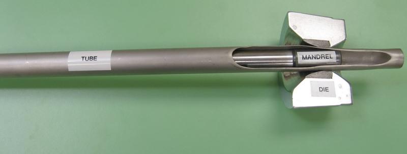
Rod Drawing. During rod drawing, a hardened steel mandrel is inserted into the bore of the tube that has been pointed. After the tube has been introduced into the die (see Figure 1), lubricating oil is pumped onto the surface of the tube, the trolley jaws grip the tube or rod tip, the trolley hook engages the chain, and the tube is drawn through the die. The die diameter determines the OD; the rod diameter determines the ID size. Proper die selection minimizes wall thickness changes before the tube contacts the mandrel.
In general, heavy-wall tubes tend to thin before contacting the rod; light walls thicken. High-angle dies tend to thin the wall and low-angle dies tend to thicken the wall. It is critical to remember that the optimum die angle varies with the diameter-to-thickness (D/t) ratio.
After the tube is drawn, it must be expanded for rod removal. A common method is to apply pressure by rotating the tube while passing it through cross rolls. This process generates radial stresses and expands the tube. The process is repeated until the tube is at finished size.
Advantages of rod drawing are that drawing speeds are relatively high and high area reductions (approximately 45 percent for stainless steel) are possible. Disadvantages are that it is a two-person operation and it requires an additional drawing operation, such as a plug draw or sinking, to remove the spiral pattern.
Plug Drawing. Two varieties of plug drawing are fixed and floating. Fixed plug drawing uses a hollow rod anchored at the back of the bench. A lubricant is pumped through the rod to a small hole near the front, allowing lubricant to enter the ID of the tube. A slightly tapered tungsten carbide plug is threaded or brazed onto the end of the rod; the tube is loaded over the rod, lubricant pumped onto the OD surface, and the tube is drawn.
One of the benefits of fixed plug drawing (see Figure 2) is that it produces a smooth ID. Another advantage is that the taper makes it possible to adjust the ID to meet a tight tolerance. While it requires only one operator, the drawing speed is quite slow, and maximum area reductions are low—about 25 percent for stainless steel.
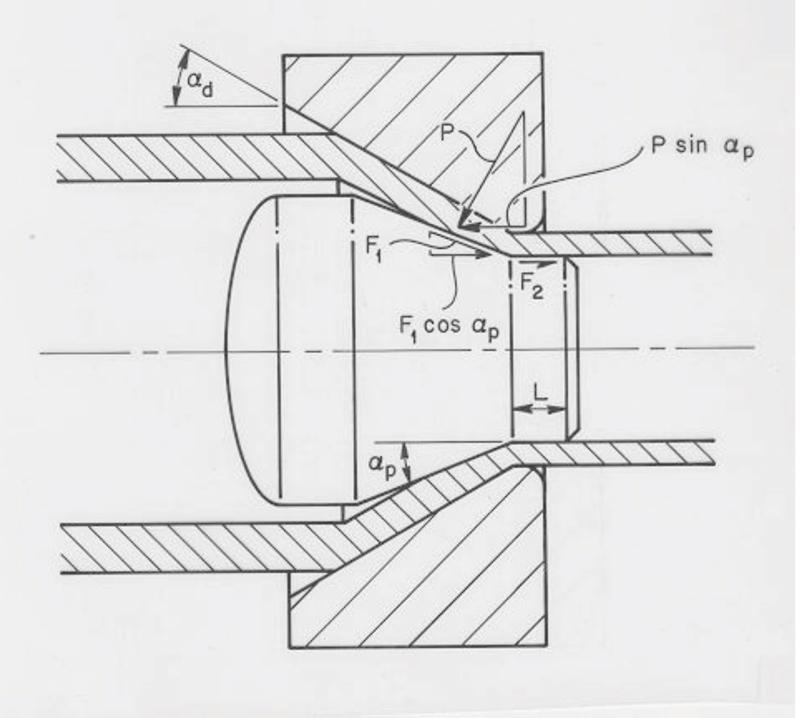
Floating plug drawing (see Figure 3) is well-suited to producing long-length coils economically. This method was used for drawing copper and aluminum for many years. After the lubricant is pumped into the ID of the tube, a tapered plug is inserted, the tube is crimped to hold the plug in place, and the tube is pointed. During drawing the plug is held in position by a combination of forces between the tube ID and the plug. The tooling design is critical to the success of this process. Die angles are generally between 28 and 32 degrees, with plug angles between 20 and 24 degrees. The bearing length should be about 10 to 15 percent of die diameter. Be aware that a plug that is too long can cause scratches on the ID; a plug that is too short will not seat.
Semifloating drawing and tethered plug drawing are floating plug processes adapted for drawing straight lengths. The plug is attached loosely to a back rod and the tube is loaded over the rod and plug for drawing (see Figure 4).
Sinking. Sinking is the term for drawing a tube with no internal support. It is usually performed as a sizing pass after a rod draw. The proper die angle depends on theD/t ratio; a properly chosen die angle minimizes the change in wall thickness. If the wall thickens too much, the ID surface finish will deteriorate.
The bearing length is longer than with other operations, up to 50 percent of the die’s diameter, to ensure the roundness of the finished tube.
Plug drawing and sinking can be used to draw a tube to a finished size.
When designing a drawing schedule, the ratio of wall reduction to diameter reduction is an important quality consideration. Wall reductions tend to iron, or smooth, the ID surface; diameter reductions tend to roughen the surface. A convenient expression for the ratio is the Q value, which is equal to the perce nt wall reduction divided by the percent ID reduction. A Q value of 2 or higher tends to smooth the ID surface. When the schedule does not lend itself to a series of high-Q-value draws, it is better to use a high-Q-value rod draw followed by a hard sink rather than a series of low-Q-value drawing operations. High Q values also result in low residual stress levels for cold-worked tubes. In a recent project, a Q value of 0.91 yielded a residual stress of more than 52,000 pounds per square inch (PSI) as measured by the Sachs and Espy procedure described in ASTM E1928. A draw with a Q value of 2.2 had a residual stress level of only 5,200 PSI. High Q values would result in negative, or compressive, values.
Lubrication. Lubrication is another important consideration, along with tooling and drawing schedule. Most tube mills use chlorinated oils for lubricating stainless steels and nickel alloys. The correct viscosity can be as low as 8,000 SUS (Saybolt Universal Seconds) or more than 100,000 SUS depending on the alloy, tube size, and type of reduction.
4. Straightening
Straightening is usually performed using a six- or 10-roll rotary straightener (see Figure 5) with a combination of flex and pressure. While flex has little effect on properties, pressure tends to increase yield strength and raise the residual stress level. Exerting the minimal pressure is the best practice.
5. Finishing
Finishing operations may include polishing, pickling, or sandblasting to improve the surface appearance and remove minor imperfections. Final inspection techniques are determined by the customers’ order requirements.
The editors of TPJ-The Tube & Pipe Journal® thank the Tube & Pipe Association, International®’s Extrusion, Drawing & Tube Reducing Technology Council for its efforts in arranging the publication of this article.
About the Author
About the Publication
subscribe now

The Tube and Pipe Journal became the first magazine dedicated to serving the metal tube and pipe industry in 1990. Today, it remains the only North American publication devoted to this industry, and it has become the most trusted source of information for tube and pipe professionals.
start your free subscription- Stay connected from anywhere

Easily access valuable industry resources now with full access to the digital edition of The Fabricator.

Easily access valuable industry resources now with full access to the digital edition of The Welder.

Easily access valuable industry resources now with full access to the digital edition of The Tube and Pipe Journal.

Easily access valuable industry resources now with full access to the digital edition of The Fabricator en Español.
- Podcasting

In this episode of The Fabricator Podcast, Caleb Chamberlain, co-founder and CEO of OSH Cut, discusses his company’s...
- Trending Articles
1
Zekelman Industries to invest $120 million in Arkansas expansion

2
3D laser tube cutting system available in 3, 4, or 5 kW

3
Corrosion-inhibiting coating can be peeled off after use

4
Brushless copper tubing cutter adjusts to ODs up to 2-1/8 in.

5
HGG Profiling Equipment names area sales manager
