


Application Engineer
Once a 3D-printed die has undergone final surface finishing (when necessary), hardening, quenching, and tempering, the completed A2 die tooling is ready for testing and production.
A priority of any manufacturing process is to deliver high-quality parts as efficiently as possible. To actualize this goal, stamping has repeatedly evolved to become more productive and cost-effective. In the past two decades alone, software simulation tools have streamlined stamping die design, and the introduction of servo presses has increased flexibility and line throughput. However, even with process efficiency at the forefront of stamping innovation, there have not been major upgrades to die component manufacture in the past 100 years.
The absence of a die build evolution is not because the die production process has been optimized. In fact, it has long been an arduous, expensive affair. Die components are typically made of tool steels with low machinability and, as with any process dependent on CNC bandwidth, the design flow of stamping tools can be tedious.
Design rework bogs down the die manufacturing process, so engineers often rely on simulation rather than prototype iteration to verify tooling designs. While computer simulation is powerful (and necessary), the inability to physically test tools before investing in final die production risks costly tooling redesigns.
Many challenges with stamping die production can be attributed directly to the machining process. The laws of physics are not on the side of expediency when it comes to machining tool steels. There are strict trade-offs between geometric complexity and cost. Lead times of weeks to months are the norm.
What the stamping industry needs is a new way to make metal die components.
As metal 3D printers are becoming more reliable and less expensive, they offer a new method for producing industrial tooling. Integrating additive manufacturing into the stamping tool production work flow can offer some distinct advantages.
Shorter Lead Times. While the time to 3D-print a part is longer, typically, than the time the same part would spend on a mill or lathe, printers run unattended and require minimal labor and training to operate. Paired with the absence of CAM in the 3D printing work flow, this results in lead times that are often weeks faster than parts ordered from a machine shop or manufactured through an internal queue.
Geometric Complexity at Lower Costs. Because additive manufacturing is done by building parts layer by layer, it is free of many constraints that come with traditional manufacturing. Sharp internal corners, undercuts, and complex surfaces are not prohibitively expensive to produce via 3D printing.
Machine Shop Optimization. Not having to machine die components from scratch helps avoid tool wear and frees up valuable machining bandwidth for other parts. With so much hardware involved in the stamping process, parallelizing the manufacture of die components can get a line up and running faster.
Integration. Although metal additive manufacturing can be easier and less expensive than machining, it is not going to replace the ways metal components are manufactured currently. Traditional methods still make the most sense for many parts. Metal 3D printing is simply another tool to add to a tool- and diemaker’s arsenal.
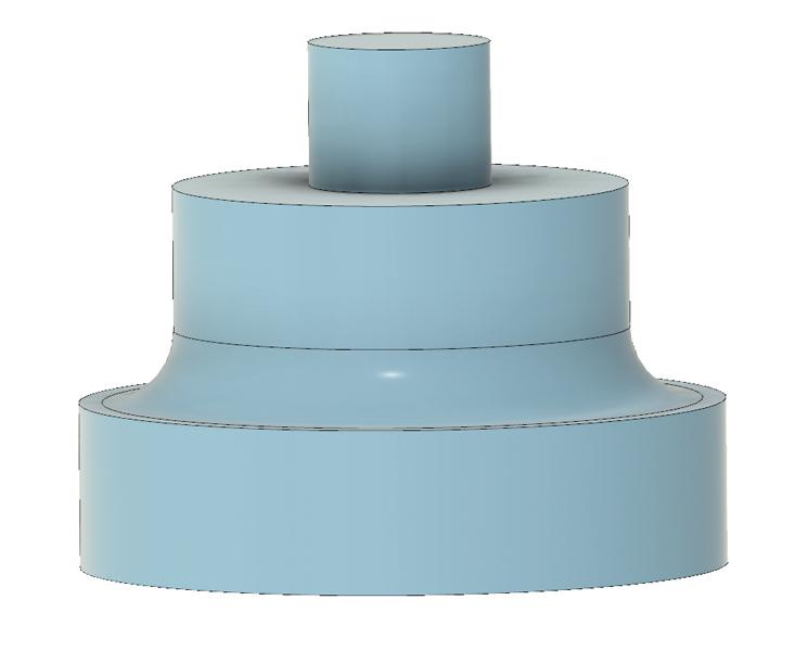
Figure 1
This is a completed CAD model for a washer punching tool. The same software that is used to design machined parts can be used for 3D-printed components.
Because of their large, regular geometries, components such as die plates, shoes, and guide pins are best machined from stock or bought off the shelf.
But, with the ability to 3D-print complex shapes with hardenable tool steels like A2 and D2, working die components for cutting, punching, and bending are good prospects for metal AM. Wear plates and heel blocks can be 3D-printed as well, offering an easier way to produce complex, high-wear components.
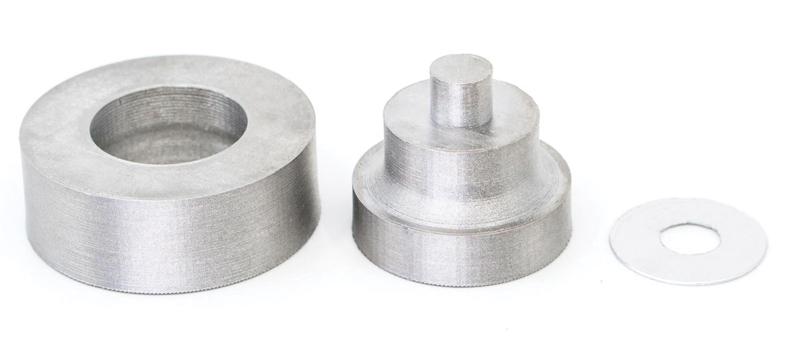
An example of a stamping die component that can be produced via metal AM is a custom washer blanking and piercing die (see Figure 1).
Producing tools using AM begins the same way as with machining: an engineer creates a 3D design in computer-aided design (CAD).
The engineer then imports the files into a metal forming simulation software to verify stamping die performance based on the necessary parameters. After the design is tested in simulation, appropriate CAD tweaks are made.
This is where the diemaking process deviates. For a die headed for CNC machining, the die designer or engineer would make cutting tool selections and determine toolpaths in a CAM software. Because this part is being 3D-printed, CAM is not a necessary step. Instead, the die designer converts the CAD file to a stereolithography (STL) file, which is the industry-standard file type for 3D printing. Users then import it into a 3D printing slicer. Here, the program automatically determines the 3D printer toolpaths to produce the part (see Figure 2).
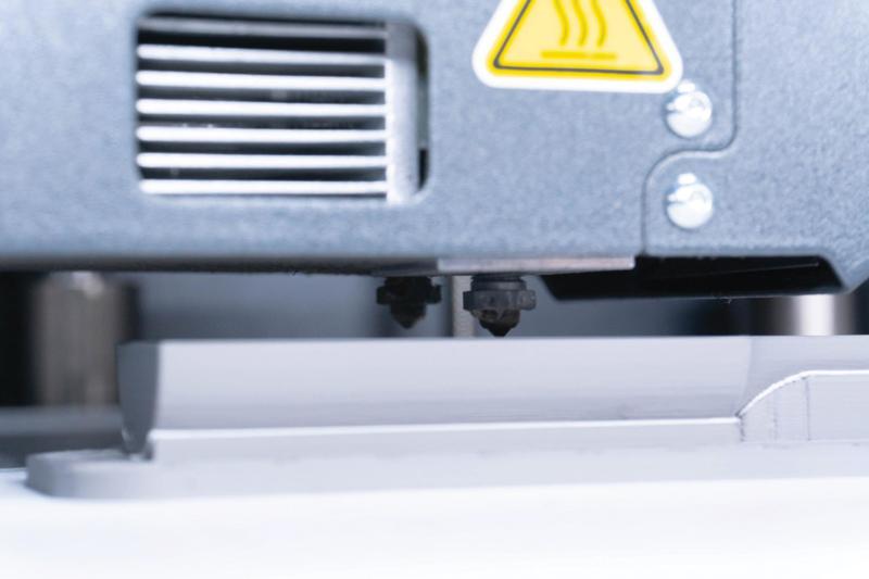
The sliced file is then sent to the machine to be printed. Depending on the size and geometry of the die component, builds can take anywhere from hours to a few days to complete. As previously mentioned, 3D printers can run unattended, so components often are printed overnight or on the weekend. The washer stamping die in Figure 2 was produced in about four days.
The next step varies, depending on the nature of the die application. Metal 3D printing is typically accurate to several thousandths of an inch, which, in many cases, is accurate enough for the working surface of a stamping die. In other situations, the die must adhere very tightly to the original design. When this is the case, the metal printed part can be postmachined to the appropriate tolerances. Even when a specification necessitates a finishing pass on the mill, less time and material removal are required than if the entire component had been machined.
After any postprocessing on the mill or lathe, the component is hardened and tempered, just as it would be with a machined A2 tool steel part. At this point the die component is ready to be fixed to the shoe for testing and production.
Cost, Time Savings. In this situation, it was more cost- and time-efficient to 3D-print the working surfaces than using traditional die milling methods. If the die manufacturer had machined these parts, the cost would have been around $720 per set, with a lead time of two weeks. By 3D-printing the tool, the diemaker cut the cost to about $100 per set, with a turnaround time of four days.
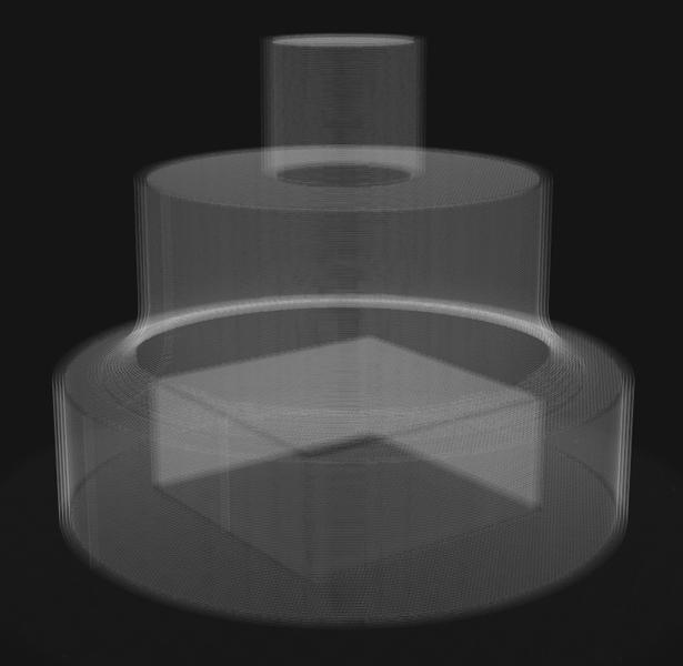
Figure 2
This screen shot of the piercing and blanking tool in a slicing software used to automatically create the metal 3D printer toolpaths shows how the washer die component will be configured.
More is to be learned about the role of metal 3D printing in the production of stamping dies. So far, the applications show clear promise.
Short Runs. Metal 3D printing is an attractive option for low-volume metal forming projects. Stamping runs that don’t comprise enough parts to justify the steep costs associated with traditional tooling can become feasible when metal 3D printing is used. A lower tooling cost upfront paired with condensed lead times makes for efficiently executed short runs.
Die Prototypes. AM lends itself very well to prototype stamping dies for smaller components. The ability to cut out CAM and reduce time on the mill opens opportunities to iterate on tool designs to find the most optimized solution. Additionally, finalized stamping die prototypes can form parts while production tooling is being machined, increasing throughput.
Complex Geometries. The more intricate a geometry is, the more expensive and time-consuming it is to produce on a mill. Machining complex geometries takes more time to process in CAM, involves multiple tool changes, and sometimes requires the stock to be milled in more than one orientation. Additive manufacturing can build complicated geometries without the added process and complexity of making it. 3D printing may be a means to develop and build complex geometries more cost-effectively than milling in many circumstances. This means more complex dies at a lower cost.
For the first time in the recent history of stamping, a new way to create die components is emerging. Metal AM presents an opportunity to expedite the tool and die manufacturing process, thereby decreasing the investment to stamp parts. As AM continues to be adopted by stamping manufacturers, it will be exciting to see how the technology is further integrated into the die production work flow.
Nick Martin is an application engineer for Markforged, 480 Pleasant St., Watertown, MA 02472, 866-496-1805, nick.martin@markforged.com, www.markforged.com.
In metal additive manufacturing, the component or part is built up layer by layer, allowing for more complex geometries.


The Fabricator is North America's leading magazine for the metal forming and fabricating industry. The magazine delivers the news, technical articles, and case histories that enable fabricators to do their jobs more efficiently. The Fabricator has served the industry since 1970.
start your free subscription
Easily access valuable industry resources now with full access to the digital edition of The Fabricator.

Easily access valuable industry resources now with full access to the digital edition of The Welder.

Easily access valuable industry resources now with full access to the digital edition of The Tube and Pipe Journal.

Easily access valuable industry resources now with full access to the digital edition of The Fabricator en Español.
In this episode of The Fabricator Podcast, Caleb Chamberlain, co-founder and CEO of OSH Cut, discusses his company’s...


