


Product Manager
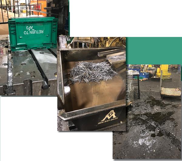
Lubricant on the floor, on the die bed, and in the scrap bin are some symptoms of an ineffective lubricant application system.
Every metal stamping process has, at its core, three key components that contribute to its overall success: the work material being stamped, the proper tooling, and the correct lubricant to help aid material flow inside the tool.
A successful stamping operation requires that all three components are carefully selected to achieve their desired purpose. The part material is chosen for the desired strength of the finished part. The tooling is designed to produce the required part geometries. The lubricant is specified for its friction-reducing performance between the part material and the tooling.
However, an important aspect of lubrication—the method of applying the lubricant in the actual production setting—is frequently overlooked during the process design stage, but it is as critical as the lubricant itself.
Selecting the proper lubricant for a stamping process is not a trivial process. A whole field of study, referred to as tribology, exists for understanding the interaction between two moving surfaces in contact with each other. Studying tribology helps increase the understanding of critical operation parameters within the metal stamping process, such as friction, wear, and lubricity.
Tribologists and lubrication engineers often run several tests to determine how well a particular lubricant will work between two surfaces. During these tests, lubricant is applied between a material that is a proxy for the tooling and a second material that is a proxy for the part material.
Lubrication evaluation tests include the cup draw test, twist-compression test, pin and V-block test, 4-ball wear test, and ball-on disk test. Each of these tests simulates the stamping process. The test lubricant can prove its effectiveness within the scope of the test.
While each of these tests is slightly different, each is useful for verifying certain parameters of the process. At the most basic level, all of these tests will measure how much force is required to get the two surfaces to move relative to one another for a given contact pressure between two surfaces. The tests also can determine at what point things start to fail. A series of controlled tests can be run to evaluate the performance of lubricants.
However, the actual delivery method of lubricant to the process is often an afterthought, and this afterthought can lead to incredible inefficiencies within the overall process. It’s just as important that the proper amount of lubrication be applied to the tooling or material in the right place at the right time.
An ineffective application method can defeat the purpose of the lubricant’s properties that have been so carefully tested and specified.
At least three negative symptoms within the stamping process are a red flag that the application process is not a good fit:
Lubricant that is wasted is not serving its intended purpose.
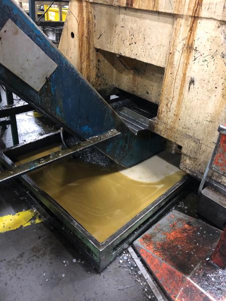
Mess. The first symptom is a wet, slippery, greasy mess as a result of lubricant overapplication. When a system is not specified to deliver the lubricant where needed, neatly and properly, the alternative is to apply a lot of lubricant everywhere.
When lubricant is overapplied, the parts, scrap, and tooling coming out of the press leave trails of lubricant throughout the facility by part bins, dies, and forklifts. This causes unsafe, slippery conditions; requires excessive part cleaning; and creates an overall messy environment. Too often operators live by the motto that more is better; however, with lubrication this is not always the case.
Inadequate, Inconsistent Coverage. The second symptom of an inadequate lubricant application system is spotty, inconsistent coverage. Stamping processes are impeded by dripping nozzles, misaimed spray tips, and a lack of process monitoring to ensure proper lubricant delivery. Part quality and tool life can suffer. Part cracking and premature tooling wear lead to excess scrap and increased machine downtime.
Waste and Cost. The third symptom of an inadequate lubricant application system is wasted lubricant as evidenced by full press pits and empty lubricant dispensers. When lubricant ends up on the floor, it is no longer carrying out its intended purpose. Frequent pumping and disposal of fluids from press pits is a large, unnecessary charge. Washing parts that are covered with excess lubricant is an added expense as well.
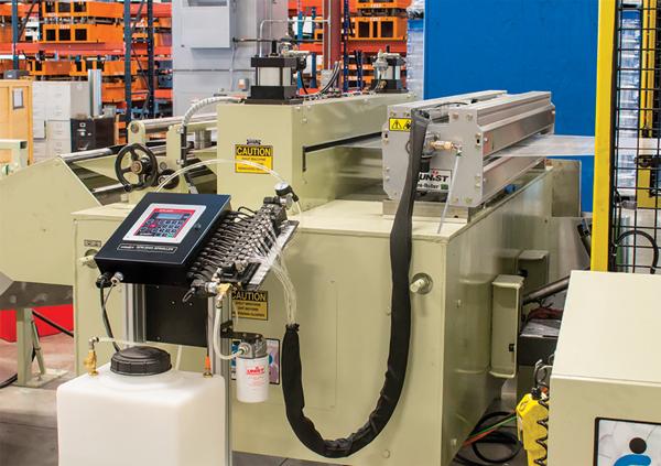
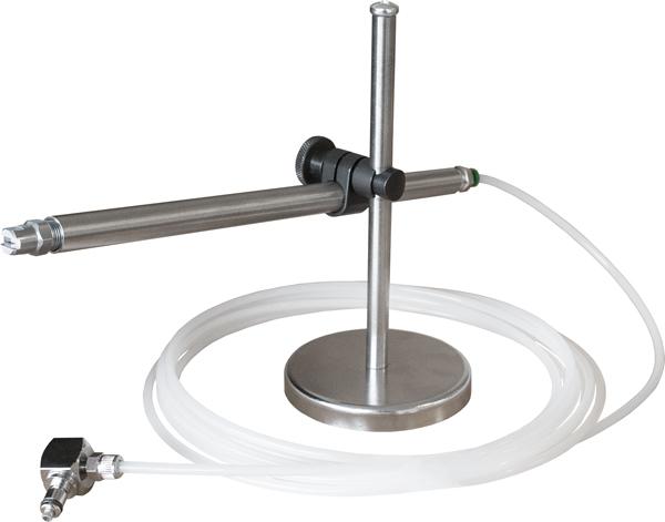
Two basic methods for applying lubricant to a part are contact and non-contact.
Contact methods include applicators that roll coat, wipe, or submerge and squeegee the material. Contact applicators can provide the neatest application and provide consistent coatings over the entirety of the part material, top and bottom.
Noncontact lubrication generally refers to a spray type of application. Spray applicators can use airless spray, air-assisted spray, or electrostatic spray nozzles. Each of these has its place, but the main benefit of noncontact lubrication is that nothing but the fluid physically touches the material. Noncontact lubrication does sometimes require an overspray management system.
Deciding which type of application system to use will depend on several factors, such as the end customer’s requirements, how flexible the system needs to be to adapt to other jobs running on the same line, and whether the line will be fed with blanks or coil stock.
When specifying a lubricant application system, metal stampers should identify the proper application location, make sure there is adequate space for the system, and assess the fluid’s aptness for application.
They must decide if both the top and bottom of the part or tooling need to be lubricated. They must also decide if the lubricator should apply fluid evenly across the width of the stock material, or if it should be applied only to sections of the part. Critical parts should be lubricated with applicators that provide feedback of proper application.
Cleaner shop environments, safer workspaces, decreased lubricant consumption, increased uptime, and better part quality are all tangible benefits of proper lubrication application.
They must also ensure that there is physical space in the line to mount the lubrication system. Line layout drawings should include the necessary space to mount a lubrication applicator and its supply. Roller or wiper applicators typically require about 12 to 15 inches of space along the direction of material flow into the press. They also usually require about 4 in. of space to the left and right of the material. Also, if supplemental lubrication is desired in the tooling where some difficult drawing or forming might occur, tooling should be designed so that in-die spray nozzles can be rigidly mounted, connected, and accessed.
Also, the fluid itself must be evaluated for proper application. The aforementioned laboratory tests typically use manual means of application such as paint brushes or rollers. However, if a lubricant is to be applied in a production environment, it must be compatible with the applicator. For example, fluid with the consistency of peanut butter would be hard to spray or roll in a production environment.
As metal stampers continually seek to eliminate waste in their processes, a well-thought-out and well-designed lubrication application system can provide access to some waste reduction low-hanging fruit. Cleaner shop environments, safer workspaces, decreased lubricant consumption, increased uptime, and better part quality are all tangible benefits of proper lubrication application. Just as the specs for a press and feeder are carefully tailored to an application, so too should the lubrication application system.
Tim Bangma is product manager for Unist Inc., 4134 36th St. SE, Grand Rapids, MI 49512, 616-588-2253, tbangma@unist.com, www.unist.com.


The Fabricator is North America's leading magazine for the metal forming and fabricating industry. The magazine delivers the news, technical articles, and case histories that enable fabricators to do their jobs more efficiently. The Fabricator has served the industry since 1970.
start your free subscription
Easily access valuable industry resources now with full access to the digital edition of The Fabricator.

Easily access valuable industry resources now with full access to the digital edition of The Welder.

Easily access valuable industry resources now with full access to the digital edition of The Tube and Pipe Journal.

Easily access valuable industry resources now with full access to the digital edition of The Fabricator en Español.
In this episode of The Fabricator Podcast, Caleb Chamberlain, co-founder and CEO of OSH Cut, discusses his company’s...


