


Research Engineer, Manufacturing and Metals Research
Editor’s Note: This research is presented in three parts. Part II will report results for the D2 tool steel inserts and two types of surface coatings. Part III will discuss results for nitrided and hard-chromed D6510 and S0050A inserts.
Galling is cold welding of sheet metal particles to the surface of the stamping die. This permanent deposit often occurs when metal surfaces are in contact and sliding against each other.
Researchers at the Oakland University Center of Advanced Manufacturing and Materials (CAMM) recently conducted a study to determine which combination of die material, die surface treatment, and lubricant was most favorable for preventing galling when stamping aluminum structural parts. They used as die materials D6510 ductile iron, S0050A cast steel, and D2 tool steel, along with inserts of three tested materials, with lubricant amounts and surface treatments typically used in stamping.
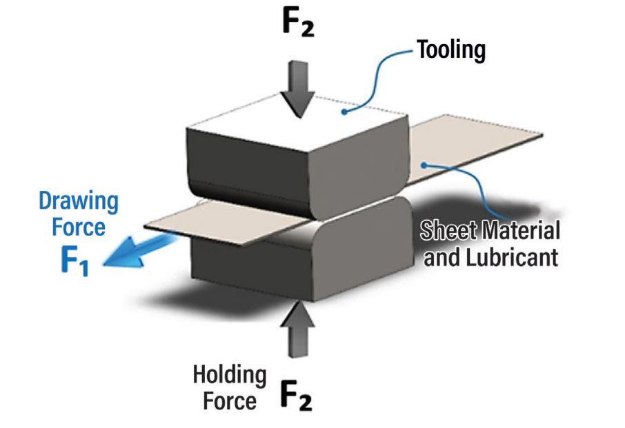
The researchers selected a simple flat-to-flat test configuration for estimating the average contact pressure corresponding to the galling onset when stamping 2.5-mm-thick AA5754 aluminum sheet. Two flat inserts of identical material and similar roughness and lubrication amount with 42- by 42-mm contact surfaces were clamped together in the draw bead simulator with a controllable amount of clamping force (see Figure 1). The tested strips were 600 mm long and 50.8 mm wide. In this configuration, the strips were wider than the tested inserts. Because the insert had a 1.5-mm radius on the edge, the effect of the edge of the contact between the strip and the die insert was less pronounced.
Tested strips were pulled between two clamped inserts at 1,000 mm/min. for all reported tests. Holding force began at 13 kN, the minimum possible holding force of the draw bead simulator, and increased to the clamping force level at which galling was observed. If sheet material deposited on the insert surface, researchers removed the deposit with 1,200-grit sandpaper, then used acetone to remove dirt and particles.
Three lubrication conditions were compared: 61AUS mill oil (50 mg/ft.²), Drycote 2-90 (DC 2-90), and dry with no lubricant. An NG2 sensor measured lubrication thickness in six locations on each side of the strip testing area.
Galling often is preceded by scratches on the sheet metal surface, and overall scratching and galling can be detected by monitoring the pulling force/sliding displacement curve on the testing machine. If the pulling force remains almost constant during the experiment, it means that no additional resistance from the tested sheet metal occurred.
While reporting the results on the pulling force and detecting changes on the contact surface, the researchers presented the results in the form of average coefficient of friction (COF), determined based on Coulomb friction law. Friction forces act on both sides of a strip drawn between two opposing flat inserts, and COF is calculated using the formula µ = F₁/2F₂ (see Figure 2).
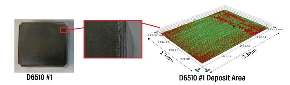
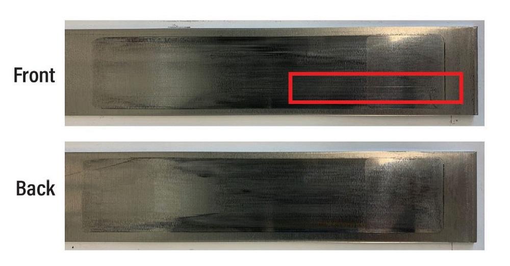
The researchers determined galling onset by examining the inserts and measuring the galling area using a Bruker profilometer. Figure 3 shows both D6510 inserts when galling was determined for DC2-90 lubricant. Deposits on the profile are shown in red. Note that the deposits of aluminum blank on the die insert surface were more common closer to the edge of the insert. Even though the strip was wider than the insert, squeezing lubricant from the contact surface might be easier in the area close to the edge of the insert.
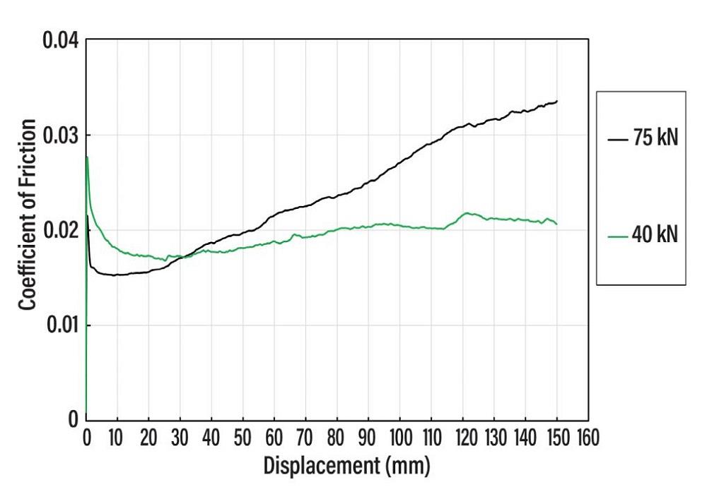
The researchers calculated COF according to the formula using the pulling force measured by an Instron load cell and clamping force calculated from the pressure in the draw bead simulator hydraulic cylinder. The COF curves for the D6510 inserts with DC2-90 lubricant are presented in Figure 4. Overall, the COF was very low with DC2-90, which allows forming of complicated shapes and deeper draws. A moderate increase in COF usually indicates scratches on the sheet surface, while a quick rise indicates galling initiation. In Figure 4, the curve begins to rise at 70 kN of force.
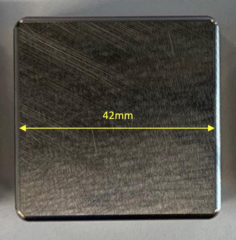
FIGURE 1. Two flat inserts with 42- by 42-mm contact surfaces were clamped together in the draw bead simulator.
Scratching often happens at the same time as the deposit appears on the insert, but in the case of D6510 with DC2-90, scratches appeared at 40-kN clamping force, before galling appeared on the inserts (see Figure 5). As clamping force increased, more scratches appeared until galling was observed at 70-kN force.
For the S0050A inserts with 50 mg/ft.2 of 61AUS, galling started at 45-kN clamping force. With DC2-90, galling started at 50 kN. With no lubricant applied, galling started at 13-kN clamping force.
For the D6510 inserts with 50 mg/ft.2 of 61AUS, galling started at 40 kN. For the same inserts with DC2-90, it started at 70 kN (with scratches observed at 40 kN), and with no lubricant applied, galling started at 13-kN clamping force.
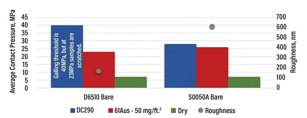
Figure 6 summarizes the average contact pressure corresponding to galling, taking into account insert surface roughness before the test. Initial roughness of the insert surface before the test was 606 nm for S0050A and 165 nm for D6510. For the S0050A inserts with 50 mg/ft.2 of 61AUS, galling started at 26 MPa of average contact pressure. For the same inserts with DC2-90, galling started at 28 MPa, and dry inserts showed galling at 7 MPa.
For the D6510 inserts with 50mg/ft.2 of 61AUS, galling started at 23 MPa of average contact pressure. With DC2-90, galling started at 40 MPa (although scratches were observed on the sample at 23 MPa). With no lubricant applied, it started at 7 MPa.
The galling threshold was highest when DC2-90 lubricant was applied to S0050A and D6510 and lowest when no lubricant was applied. Dry spots are certainly very harmful from galling perspective.
This research project was funded in part by the United States Council for Automotive Research with contributions from Novelis Corp., which provided 5754 aluminum alloy coil; Ionbond LLC, which performed coatings of tested inserts; and Quaker-Houghton, which provided lubricants and technical recommendations for application. Dr. Dajun Zhou from Stellantis provided very useful comments and actively participated in discussion of conclusions for the project.

Professor and Director
Oakland University Center of Advanced Manufacturing and Materials (CAMM)

PhD Candidate
Oakland University Center of Advanced Manufacturing and Materials (CAMM)


The Fabricator is North America's leading magazine for the metal forming and fabricating industry. The magazine delivers the news, technical articles, and case histories that enable fabricators to do their jobs more efficiently. The Fabricator has served the industry since 1970.
start your free subscription
Easily access valuable industry resources now with full access to the digital edition of The Fabricator.

Easily access valuable industry resources now with full access to the digital edition of The Welder.

Easily access valuable industry resources now with full access to the digital edition of The Tube and Pipe Journal.

Easily access valuable industry resources now with full access to the digital edition of The Fabricator en Español.
In this episode of The Fabricator Podcast, Caleb Chamberlain, co-founder and CEO of OSH Cut, discusses his company’s...


