


Die design software helps optimize energy absorption, weight targets
Software simulation allows stamper to calculate formability accurately

Die design software for lightweighting. Getty Images
GNS North America is a Tier 1 supplier of press-hardened steel (PHS), or hot-stamped; cold-stamped components; and welded subassemblies for the automotive industry.
Founded in Korea in 1971, the company employs approximately 550 people and operates 16 active PHS stamp lines, 10 cold-stamp lines, and various assembly and weld cells. Its plants are in Holland, Mich., Canton, Mich., and San Jose Iturbide, Mexico.
The engineering team at GNS North America experienced challenges with producing parts to achieve energy absorption and weight targets.
Challenges With PHS, Tailored Blanks
GNS’s daily production and quoting challenges were:
PHS Parts. Components are becoming more complex, both in their geometry and because of weight-saving thickness-reduction initiatives. This combination introduces unique challenges to tooling and process development. The industry is constantly striving for weight savings, driving GNS North America to hot-stamp more parts out of PHS, or boron-manganese steel (see Hot-stamped Steel Primer sidebar).
Hot stamping produces components that are residual stress-free, possessing both high yield and tensile strength properties. However, because of the resulting hardness, tight-tolerance hole and slot features and trim edges have to be laser-cut in a secondary process, which can be expensive.
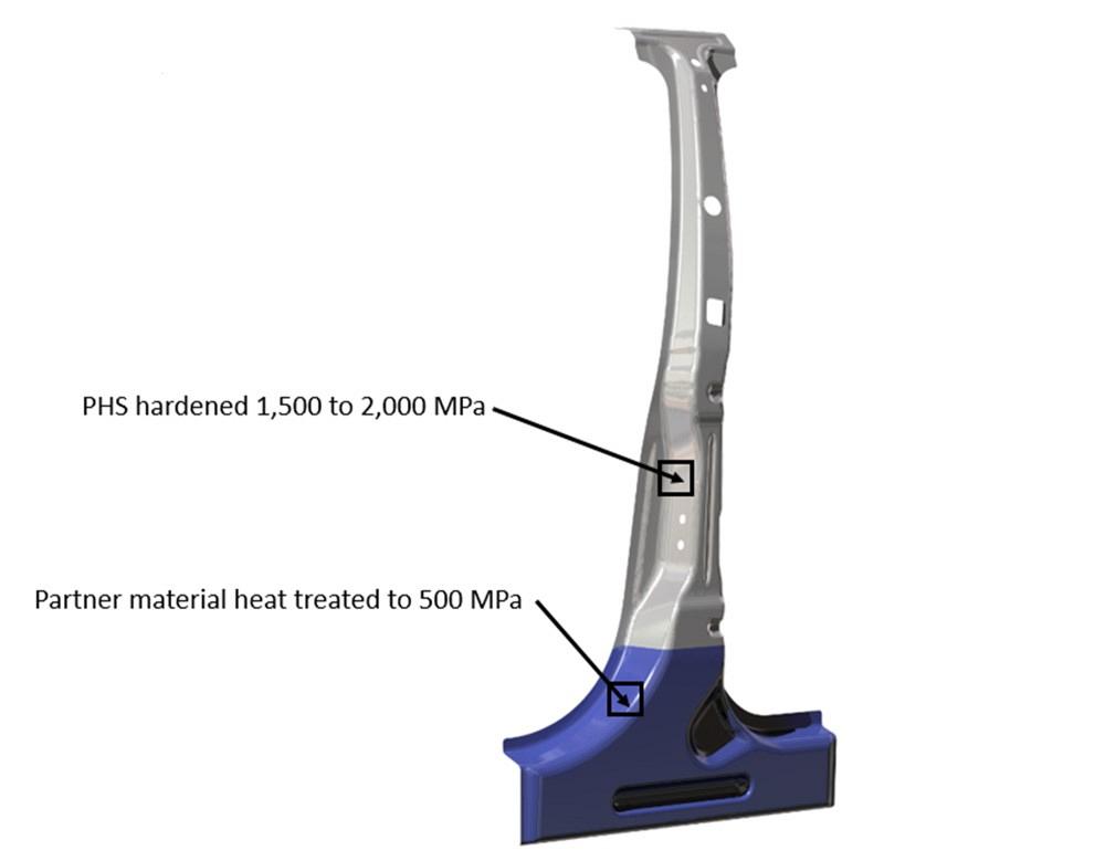
Tailored Blanks. Customers also demand components with optimized energy absorption performance for safety goals as well as weight targets. These requirements have driven GNS designs to evolve into components with multimaterial thickness and even multimaterial types. Three processes currently used that allow for these tailored designs to be manufactured are tailor welded blanks, tailor rolled blanks, and tailor patch blanks.
Tailor welded blanks (TWB) are made from individual steel sheets of different thicknesses, strengths, and coatings that are laser-welded together. This process positions the material with the right properties in the right places (see Figure 1).
Tailor rolled blanks (TRB) are sheets with a continuous transition from one thickness to another. They are made on a cold rolling mill.
Tailor welded blanks (TWB) are made from individual steel sheets of different thicknesses, strengths, and coatings that are laser welded together. This process positions the material with the right properties in the right places. Images: AutoForm Engineering GmbH
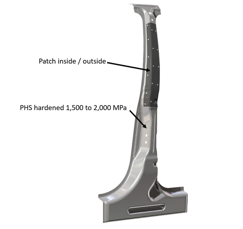
Tailor patch blanks are 2D blanks that are locally reinforced by attaching smaller 2D blanks (patches) by either spot or laser welding (see Figure 2). The patches create zones of extra thickness on the blank.
They require a unique tool design, spot weld positioning, and material thickness deltas. The designer must consider this thickness variation and model transition zones into the die cavity surfaces where the material thickness transitions from double material thickness back to single thickness. Locations of the spot welds that adhere the patches to the blank are important to prevent part failure as well as failure of the spot welds themselves.
Software Simulation Allows Accurate Formability Calculations
These challenges drove the need for simulation tools to help the GNS North America design and development teams confidently predict component formability when designing the process and tooling.
Following competitive evaluations, the stamping manufacturer chose to lease the AutoForm Simulation Software Suite as its process predictive tool. Then the engineering team could calculate formability outcomes quickly and accurately. GNS also used the simulation software to make microadjustments to the press closing speed. The team changed the blank trim lines as well.
Experienced operators at the plant encountered a low learning curve with the software. Those unfamiliar with the software received comprehensive basic training, and some took advanced training for hot stamping.
Once the team understood the simulation tool and gained confidence in the correlation between the physical and predicted results, the software provided valuable insight for all operations.
Putting the Software to Work
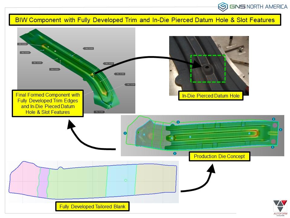
The GNS North America team produces a high-volume body-in-white component at its Canton and San Jose Iturbide facilities for a North American OEM. The team used multiple tools from the simulation software suite to successfully eliminate problems and challenges in producing the part.
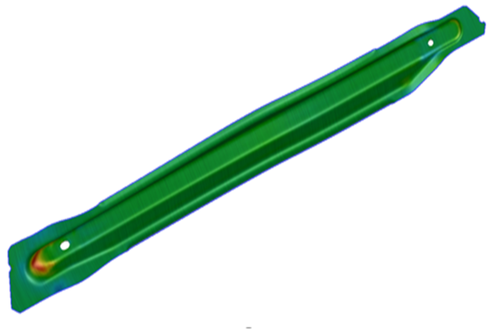
When reviewing the initial simulation, the designers could see the predicted thickening and thinning of the formed component. At this point the team needed to make decisions on how to improve the process—whether the design process needed to change, such as adding a binder and making it a draw process instead of a crash form. Another approach the team considered was to combine the crash form and draw options by adding pads to the crash form to control specific areas of the sheet to either reduce or promote material flow. These adjustments could be made early in the design process.
This is a representation of a tailor patchwork blank.
Eliminating Laser Trimming. The team initiated the process by using the software’s iterative features to optimize placement and timing of the required pads and binders. This iterative approach allowed for multiple simulation attempts to be completed in rapid succession.
Next it used the iterative trim development capability of the simulation software to generate the optimized 2D blank profile that would adhere to the customer’s required trim edge tolerance. The software analyzed the sheet boundary to “best fit” the target boundary and made automatic adjustments to achieve a finish boundary that fell within the defined profile tolerance. These iteration loops gave the stamper an opportunity to maximize equipment processing efficiencies. It also allowed more of the part to be fully developed so that less laser trimming was required. The manufacturer then shared that information with its customers to maintain their competitive edge.
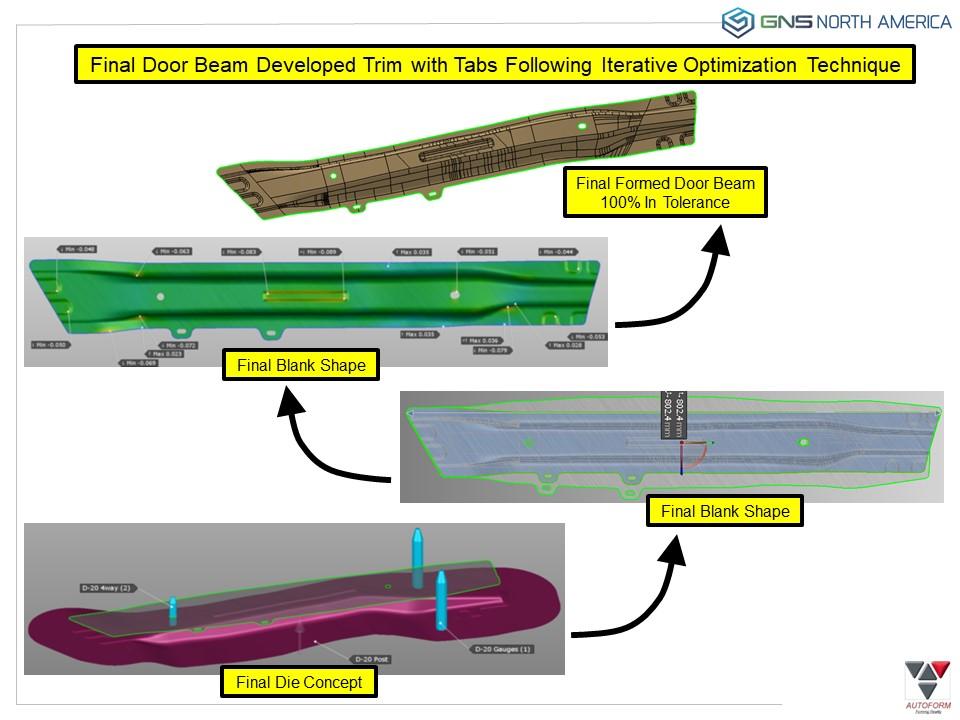
GNS developed the trim lines on most side impact beams using the software (see Figure 3).
In-die Piercing. During these process optimizations, the team recognized an additional opportunity to incorporate in-die pierce technology. Though adding complexity to the PHS die set, this hardware allowed for the critical locating datum hole and slot features to be added during the hot-stamping operation and avoid the secondary laser operation.
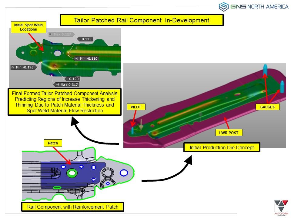
Tailored Patch Blank. In addition, the OEM required that the component weight be minimized and use a tailored thickness blank. This would have required costly upfront development using traditional techniques. However, the team was able to apply its experience with the simulation software to expedite the optimization and suppress the cost.
The GNS team used the software’s patch simulation capabilities to establish patch-blank spot weld patterns. The spot welds that adhere the patches to the blank also had to be evaluated to ensure that their placement would not disrupt the needed material flow or fracture during the forming process. To set up the simulation, the team defined the number and location of spot welds. The results of this initial setup gave the team an opportunity to visualize the normal and tangential forces exerted on each spot weld during the forming process. These analytical results guided the team to predict interfacial weld failure and revise the spot weld pattern to eliminate the undesired condition.
The software’s graphical user interface gave the manufacturer time to schedule and process multiple simulations quickly, support the processing of large RFQs, study and fine-tune more challenging components, and develop blank profiles. Using the AutoForm-ThermoSolver, the team could see the dilatation that heating the 22MnB5 material blanks caused. It could study the effects of the transfer time on the heated blanks from the oven to the tool, while referencing adherence to the continuous cooling transformation phase diagram, press forming, and quenching speeds. All of these tools gave the team information they could use to optimize their process pursuant to more efficient cycle times.
Using the simulation software suite’s iterative optimization features, GNS North America now can achieve developed trim edges and holes to initial customer quality requirements of 80% or greater for the first hits and buyoffs to support initial material required dates on both side impact beams and body-in-white components. This saves both time and money related to expensive secondary laser operations, which the company can pass through to its customers.
Hot-stamped Steel Primer
Hot-stamped parts are formed from press-hardenable steel (PHS). The PHS contains 0.001% to 0.005% boron carbon/manganese. It is most commonly known as 22MnB5.
Generic image of a single-hat section side impact beam. Note that the part has a fully developed outside perimeter trim and hole and slot features.
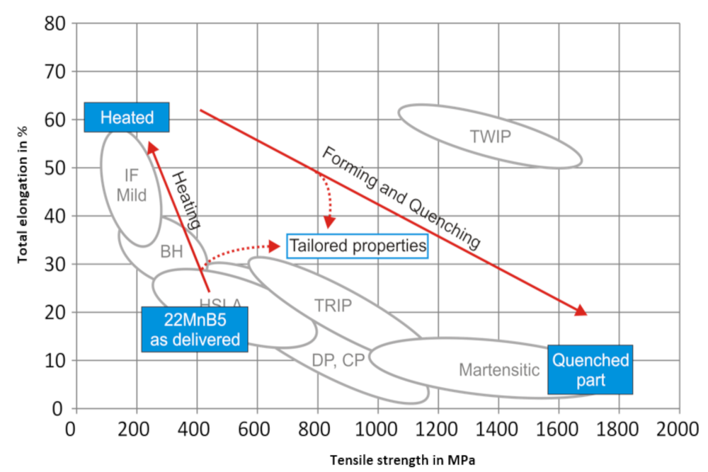
The preprocessed material has mechanical properties similar to the widely used HSLA 300 and 340 grade steels, with a tensile strength around 400 MPa and 600 MPa for 1500 grades. However, when the 22MnB5 is thermomechanically processed, its microstructure changes, resulting in a martensitic microstructure. This change is commonly referred to as a phase transformation.
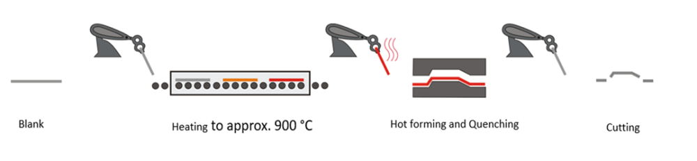
In terms of the process, first the steel is heated to around 950 degrees C and then transported from the furnace to the die and press with robotic end-of-arm tooling. Once the blanks are properly located in the die cavities, the press cycles and the upper die half closes on the lower die half to form the part to its final shape and dwell, while special water-cooling channels in the die forms rapidly extract the heat from the blanks (see Image 1).
The combination of the high temperature and the rapid cooling transforms the material into a 100% martensitic part that can have a finished tensile strength of up to 2,000 MPa. If all this is done accurately, parts can be produced within 100% tolerance and without springback.
Image 2 shows the finished martensitic steel’s tensile strength and elongation overlaid on other steels’ to visually demonstrate the differences. This is done to achieve weight targets while simultaneously retaining high-strength mechanical properties for overall performance. This unique material behavior is key for lightweighting safety cages, A pillars, and B pillars.
This unique steel has been used in automotive applications since the early 1980s, starting with Volvo, and continues to become a preferred material selected for automotive impact and body-in-white components and subassemblies.
About the Publication

subscribe now

The Fabricator is North America's leading magazine for the metal forming and fabricating industry. The magazine delivers the news, technical articles, and case histories that enable fabricators to do their jobs more efficiently. The Fabricator has served the industry since 1970.
start your free subscription- Stay connected from anywhere

Easily access valuable industry resources now with full access to the digital edition of The Fabricator.

Easily access valuable industry resources now with full access to the digital edition of The Welder.

Easily access valuable industry resources now with full access to the digital edition of The Tube and Pipe Journal.

Easily access valuable industry resources now with full access to the digital edition of The Fabricator en Español.
- Podcasting

In this episode of The Fabricator Podcast, Caleb Chamberlain, co-founder and CEO of OSH Cut, discusses his company’s...


