


Contributing Writer
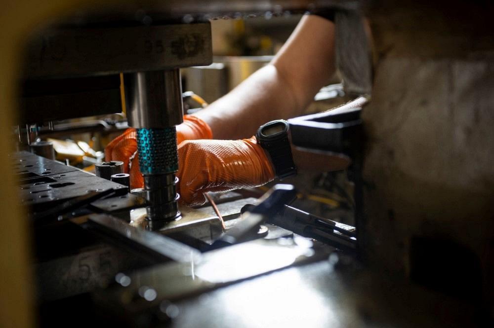
Selecting the right die guidance components is essential for stamping success, but they can’t compensate for a poorly maintained press. Image: CEP Technologies
In Part I of this two-part series, I discussed the process of selecting a die set type and thickness. Now let’s discuss various commercially available die guidance components and some basic guidelines for deciding which type is best suited for your operation.
First, let me make this statement: The function of the guide pins is to locate the upper and lower shoes or castings properly so that all of the die components mounted on the upper and lower shoe can interface with each other precisely. They guide cutting and forming components and sections so that the correct clearance can be achieved and effectively maintained. Guide pins are not intended to help guide the ram of a poorly maintained or sloppy press!
The press must be independently guided with precision.
A gentleman once told me, “Dies make parts, presses don’t.” My response was, “With all due respect, sir, both the die and the press are part of a system. Each one must function as the engineer intended it to function.” Needless to say, he was having many press-related stamping problems.
One of the statements I make in every training session I conduct is, “You can build and design a jewel of a tool, but if you put it into a glorified 200-ton trash compactor, you're going to have problems.” Don’t try to compensate for a poorly maintained or sloppy press by choosing oversized or considerably more guide pins on a die set.
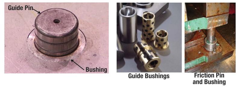
Guide pins, sometimes referred to as guide posts or pillars, function together with guide bushings to align the upper and lower die shoes precisely. They are cylinder-shaped pins made of hardened tool steel, precision-ground often within 0.0001 in. The two basic types of guide pins are friction pins (often called plain bearing pins) and ball bearing pins (also called ultraprecision guide pins). The pins fit precisely into a precision-ground sleeve called a bushing. Like guide pins, bushings often are ground to within 0.0001 in.
Friction pins (see Figure 1) are slightly smaller (usually about 0.0005 in. smaller) than the guide bushing's inside diameter. Friction pins and bushing typically cost less than ball bearing-style pins and are used commonly when a great deal of side thrust is expected in the die. Because they generate a great deal of friction, they are not desirable for high-speed stamping operations. To minimize the friction, the bushings usually are lined with a wear-resistant material called aluminum-bronze that may contain graphite plugs to reduce friction further. In addition, friction pins often are lubricated with high-pressure grease.
One common problem associated with using friction pins is that it often makes the process of separating the die quite difficult, especially larger dies. Care must be taken so that the die is separated in such as fashion that the upper and lower die shoes remain parallel during the separation process. Cocking the die may result in bending a guide pin. For larger dies, a special hydraulic machine called a die separator is often utilized to assist in the separation of the dies.
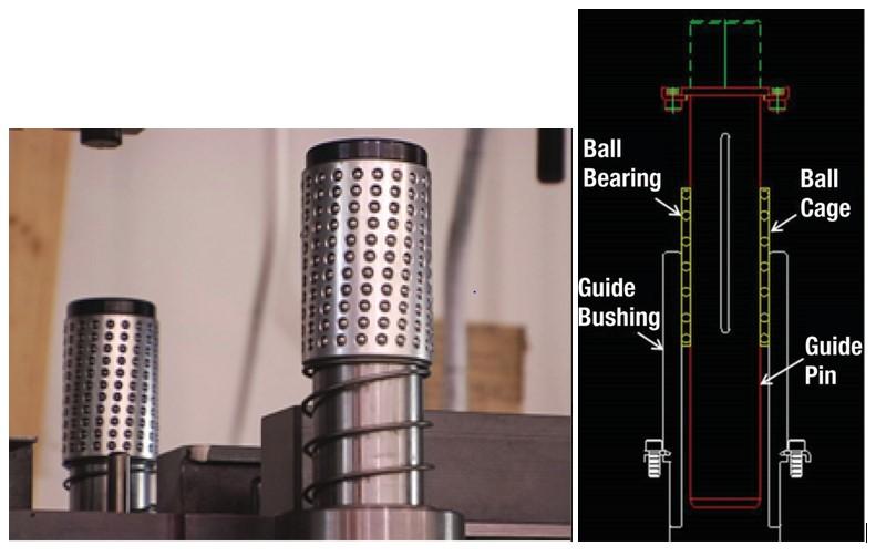
Ball bearing pins (see Figure 2) are by far the more popular choice. Unlike friction pins, these pins ride on a series of ball bearings contained in a special aluminum ball cage that permits the bearings to rotate without falling out. These pins have several advantages. First, friction is reduced, so the die can run at faster speeds without generating excessive friction and heat. This makes them ideal for high-speed operations. Second, they allow the diemakers and die maintenance technicians to separate the upper and lower die shoes easily. And third, because they use ball bearings, they can be manufactured with greater accuracy than friction pins. In fact, most people don’t realize that the pin and bearing assembly is about 0.0002 in. larger than the inside diameter of the bushing. This explains why many manufacturers refer to them as “negative slop” guide pins. Unlike friction pins, ball bearing guide pins should never be greased; lubricate them with light oil only.
Guide blocks are special steel blocks that are precision-machined, screwed, doweled, and often cast or welded onto both the upper and lower die shoes. They contain hardened tool steel components called wear plates. Guide blocks are used to align and heel dies when ultraprecise alignment is not required.
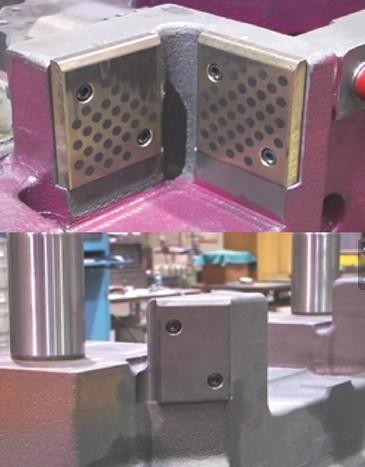
Unlike guide blocks, heel blocks (see Figure 3) often serve as a supplement to guide pins and bushings. They are especially important if the generated force is severely unbalanced or one-directional. Too much force generated from one direction can cause the guide pins to deflect, which may result in misalignment of critical cutting and forming components. Many large dies, such as those used in drawing, do not require ultraprecise alignment, so they use boxed guides and wear plates rather than guide pins and bushings. Don’t underestimate the importance of guide pins, bushings, and guidance components. Remember the importance of a solid foundation. A marble mansion with golden pillars will crumble without one.


The Fabricator is North America's leading magazine for the metal forming and fabricating industry. The magazine delivers the news, technical articles, and case histories that enable fabricators to do their jobs more efficiently. The Fabricator has served the industry since 1970.
start your free subscription
Easily access valuable industry resources now with full access to the digital edition of The Fabricator.

Easily access valuable industry resources now with full access to the digital edition of The Welder.

Easily access valuable industry resources now with full access to the digital edition of The Tube and Pipe Journal.

Easily access valuable industry resources now with full access to the digital edition of The Fabricator en Español.
In this episode of The Fabricator Podcast, Caleb Chamberlain, co-founder and CEO of OSH Cut, discusses his company’s...


