


Contributing Writer

Draw Pad Fundamentals
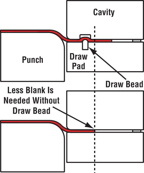
A draw pad is a pressure-loaded ring that surrounds the male forming punch and controls metal flow into the draw die cavity and over the drawing punch. Depending on the part geometry, it can be flat or contoured.
Draw pads can get their needed force from a variety of pressure systems. Common systems are gas or nitrogen springs, a press cushion system, urethane or coil springs, and hydraulic cylinders.
Draw pads usually are made from a hardened, wear-resistant tool steel or a type of hardenable cast iron (see Figure 1 ).
Draw Pad Function
Despite popular misconceptions, the true function of a draw pad is not to squeeze the metal and create a resistance to flow, but to keep the metal from wrinkling during inward flow and compression. Period.
Before you start writing that nasty letter or e-mail telling me how your company has used draw pad pressure for years with a great deal of success, please hear me out. I am in noway saying that draw pad pressure cannot be used to create a restrictive force, nor am I stating that limited success cannot be achieved by applying more or less draw pad force. However, I am saying that achieving consistency will be more difficult using these methods.
Why? First of all, unless you have a speciality system such as electronic shimming or programmable cushion, draw pad pressure on the blank normally increases as the pad travels downward during the drawing process.
For example, the pressure exerted on the blank when using a stand-alone gas spring can double during the downstroke. This is a problem because the more pressure that is applied to the blank, the greater the effects of lubrication. In simple terms, the more you squeeze the lubricant, the more it affects friction. This means that if you use draw pad pressure alone, you are relying solely on the frictional value created by the draw pad, which is inconsistent, and the coefficient of friction created by the lubricant.
Variables such as die temperature, lubricant viscosity, press deflection, forming speed, material surface, and lubricant application have great impact on the success of a drawing process. To complicate matters, as the metal flows inward, the amount of metal trapped between the die face and draw pad decreases, changing the draw ratio. This result in more pressure being concentrated on a smaller area of the blank during the drawing process.
Imagine holding a sheet of metal between your forefinger and thumb. Now imagine that I’ve asked you to apply just the right amount of force to the metal so that when I pull it through your fingers, it starches 10 percent. I don’t want 9 percent or 11 percent. And I want you to keep this 10 percent consistent for the next 10,000 times I pull it through your fingers. Your odds of success are pretty slim.
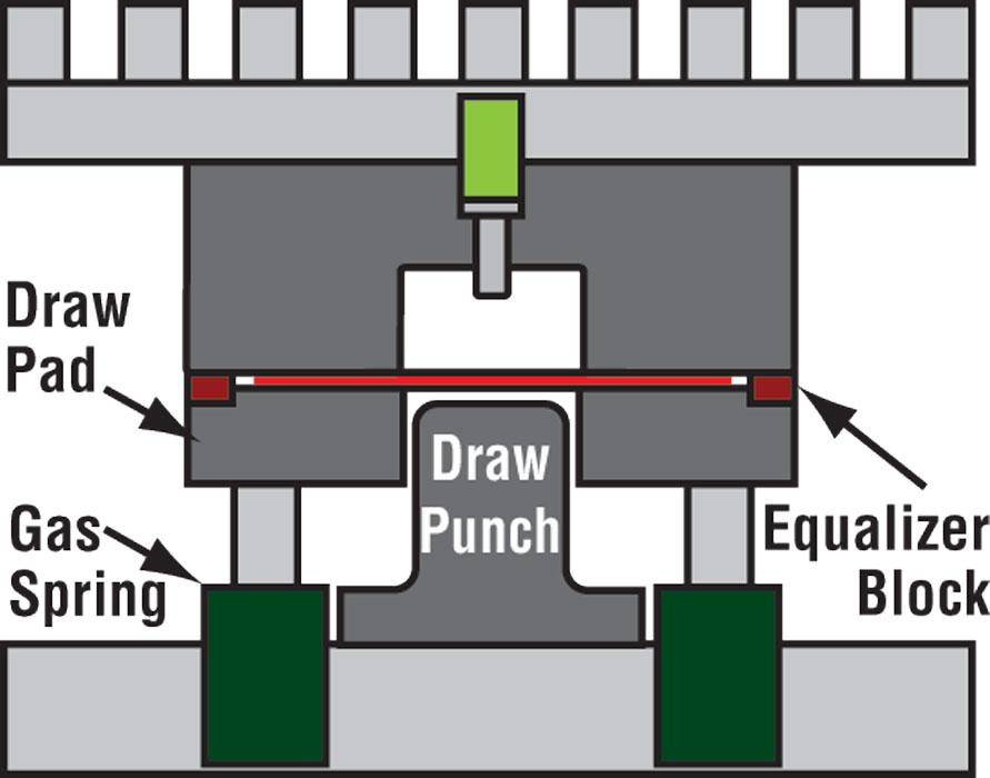
Figure 1
Draw pads usually are made from a hardened wear-resistant tool steel or a type of hardened cast iron.
Now let’s change the circumstances so that they mimic a drawing operation fully reliant on pressure and lubrication. Imagine holding the imaginary sheet metal between your forefinger and thumb again, but this time I am going to put lubricant in the metal. I want you to apply just the right amount of pressure to the blank, making sure that your pressure increases as I pull it through your hands. I want 10 percent stretch consistently for the next 10,000 times. What are your chances of satisfying my expectations? About as good as winning the lotto. You get the idea.
A Better Solution
Equalizers, often referred to as standoffs or draw pad spacers, are blocks of impact-resistant tool steel that are inserted into the draw pad or die face. Their function is to maintain a specified gap between the die face and the draw pad. They maintain this gap regardless of excessive pressure that may be exerted on the draw pad.Equalizers prevent the metal from being squeezed during the drawing process, but they also maintain a close enough gap between the die face and deletion and allow for simple adjustment to be made for minor thickness variations and mechanical property changes that occur in the sheet metal throughout the coil (see Figure 1 ).
Of course, there are exceptions to nearly every rule, especially in the world of die design and metal forming. Here are a few exceptions regarding the use of equalizers.
Until next time… Best of luck!


The Fabricator is North America's leading magazine for the metal forming and fabricating industry. The magazine delivers the news, technical articles, and case histories that enable fabricators to do their jobs more efficiently. The Fabricator has served the industry since 1970.
start your free subscription
Easily access valuable industry resources now with full access to the digital edition of The Fabricator.

Easily access valuable industry resources now with full access to the digital edition of The Welder.

Easily access valuable industry resources now with full access to the digital edition of The Tube and Pipe Journal.

Easily access valuable industry resources now with full access to the digital edition of The Fabricator en Español.
In this episode of The Fabricator Podcast, Caleb Chamberlain, co-founder and CEO of OSH Cut, discusses his company’s...


