


Technical Manager
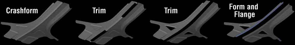
Figure 1
The forming process for an A-pillar: crashform, trim, trim again, then form.
Springback best practices, cultivated diligently over decades, have been effective in managing dimensional compliance on mild steel and high-strength/low-alloy (HSLA) stampings. However, over the past couple of decades, newer grades of advanced high-strength steels (AHSS) and high-strength aluminum alloys have upended this store of collective wisdom. Although virtual engineering tools have assumed a central role in the mitigation and management of springback for these materials, best practices for effective application of these tools are not clearly understood.
Measure, mitigate, control, and compensate is a systematic strategy that encapsulates best practices in the engineering of tools and processes to ensure they are truly capable of producing dimensionally compliant stampings. Faithfully adopted and executed, it has been proven to significantly reduce tryout costs and to ensure consistent dimensional compliance over a panel’s production life. This article reviews the engineering and simulation best practices that are crucial to successfully executing this strategy. The stamping process to produce an A-pillar (see Figure 1) from AK Steel’s NEXMET 1000 grade of generation 3 dual-phase material is used for illustration of key elements of this strategy.
The simulation should be built and matured to produce the most reliable prediction of the springback that is expected to be measured off the physical panel. This requires uncompromising diligence in simulating all aspects of the stamping process, tooling, material, and lubrication that are expected to have an influence on stamping outcomes. This includes those that are expected to be realized during physical tryout and production.
Die Condition. Pad bearing, binder gap or spotting, side-wall clearances, bottoming blocks, flange steel entry and clearances, and hard touch must be represented in simulation just as they will be realized during production.
Process. Die operational lineup, binder and pad tonnages, location of cushion pins and nitrogen cylinders, and tonnage over stroke need to be defined exactly as intended to be designed and built.
Material. Testing is indispensable for characterizing materials for simulation. Tensile testing is becoming commonplace and is useful for representing material behavior under tension. Predicting springback reliably in AHSS and high-strength aluminum grades requires tension-compression testing as well. For these materials, the commonly applied assumption in simulation that material behaves the same under tension and compression will lead to incorrect and unreliable predictions (see Figure 2).
Tension-compression testing is indeed difficult, and such data is not commonly available. However, given its importance to the prediction and management of springback in these advanced material grades, it is hoped that materials suppliers will take note and will generate and distribute this data more widely in the near future.
Friction. Friction during the forming process depends on the surface treatment on the tools, coatings if any on the tool and sheet metal, lubricant used, tool gap, sliding between the sheet and tool surfaces, and the heat generated during forming. Sophisticated modeling tools now are available to take these factors into account to represent friction conditions more accurately (see Figure 3). This capability adds reliability to simulation outcomes.
Draw Scaling. Generally, sheet metal is well-stretched in the first draw die; uniform stretch is important for part function as well as for controlling panel distortion. When the panel is unloaded from the draw die, a very small amount of this stretch is lost because of elastic relaxation, and the panel shrinks. The shrunken draw panel no longer fits on the nominal trim die.
The resulting misfit leads to unintended crushing of the panel between the trim post and pad. This problem is commonly avoided by expanding, or scaling, the draw die; when the draw panel is unloaded from the scaled draw die, it shrinks to nominal dimensions. This scaling process needs to be correctly represented in simulation.
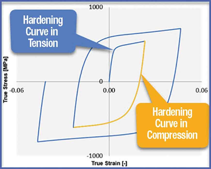
Figure 2
Hardening in tension can be quite different from hardening in compression.Hardening in tension can be quite different from hardening in compression.
Drawshell Nesting. Machining the trim die surfaces to nest the drawshell—the sprung draw panel—is another essential diemaking remedy intended to minimize the unintended crushing of the panel in the trim die (see Figure 4). This also needs to be correctly represented and validated in simulation.
Detailed Validation. The full process simulation needs to be matured and finalized, incorporating all of the previous details. Simulation outcomes from the finalized version need to be acceptable over all the required formability and quality metrics.
The common approach to finalizing a simulation is manual and iterative: Starting with an initial simulation outcome, die and process conditions are manually modified based on experience, and a new simulation outcome is generated. This review-modify-rerun-wait approach often can be time-consuming, and it may not produce an optimal outcome in terms of finalized die and process. Technology is available today that enables a more systematic and efficient approach that explores all plausible scenarios before identifying the optimal scenario.
Blank Development, Trim Line Optimization. This is important to accomplish before even reviewing springback outcomes, as changes to any of these lines will result in changes to springback as well.
Measurement of Springback in Simulation. All this diligence detailed earlier goes toward generating accurate and reliable springback outcomes in simulation. While the springback is being measured, the panel needs to be fixtured in such a manner that the fixturing process itself does not introduce additional distortion in the panel.
Once this is ensured, the measured springback needs to be observed for progression from one station to the next, and the source and type of springback identified: Bend relaxation? Side-wall curl? Oil canning? Twist? Simulation technology offers a variety of diagnostic tools to apply to such investigation. Measuring springback correctly for its magnitude and identifying the type of springback are vital to identifying the correct countermeasures to apply. Modify process? Modify product? Compensate?
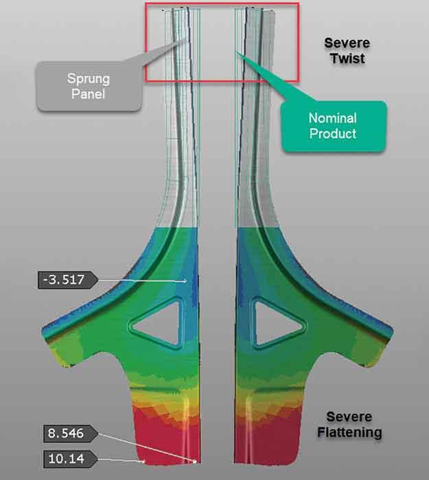
The sprung A-pillar (see Figure 5) shows severe twisting at one end and a large amount of flattening at the other end. This is to be expected, given the nature of the material, the design of the part, and the blank-saving crashform process that is used. How do we bring this panel into dimensional compliance? Considering the severity of the distortion, clearly the nominal process and dies are not ready to be compensated before some springback mitigation is applied first.
Mitigation involves the identification, and elimination or minimization, of panel distortion arising from springback modes such as side-wall curl and oil canning and the reduction of excessive amounts of springback.
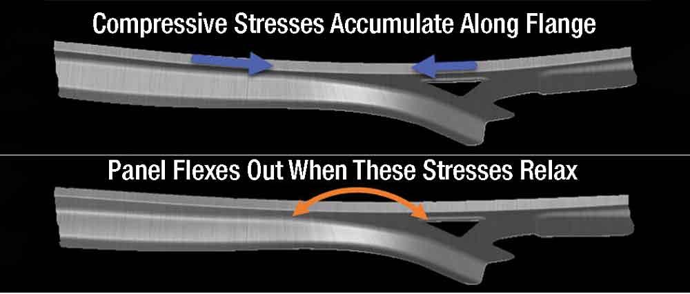
Oil canning usually is caused when strong compression develops during the forming process and is compounded on parts with simple shapes lacking geometric stiffness. Side-wall curl is produced when large stress differentials develop through the thickness of the sheet metal and along the flange lengths as they are bent and unbent over forming radii. Oil canning and side-wall curl modes of springback cannot be compensated for; these need to be identified reliably so appropriate countermeasures—product or process—can be applied. Simulation technology provides diagnostic tools that come in handy in such identification.
Likewise, large magnitudes of springback distortion and twisting cannot simply be compensated away; springback needs to be reduced to manageable levels before attempting compensation.
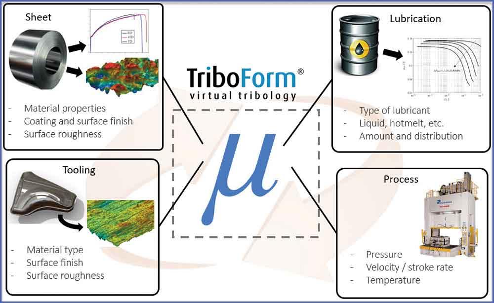
Figure 3
Realistic modeling of friction advances reliable simulation outcomes.
In the case of the A-pillar, the compression that develops on the flange as it is formed causes severe flattening toward the bottom—a classic shrink flange scenario. When this decompresses, the resulting tensile state on the flange flexes the panel outward, producing the observed flattening (see Figure 6).
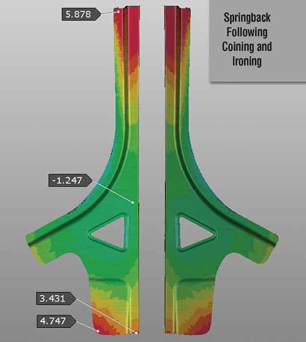
Coining and ironing are often used to mitigate springback where appropriate. In the case of the A-pillar, coining the top radius of the curved flange was attempted to reduce twist and ironing along the wiped flange to reduce panel flattening. These countermeasures, in combination, did reduce springback considerably and stabilized the panel against twisting (see Figure 7); therefore, the panel was in a much better starting point from which to attempt compensation.
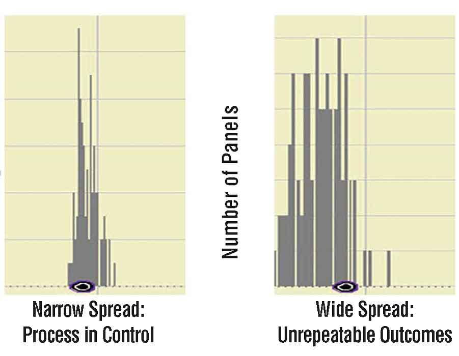
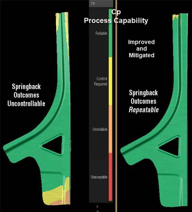
Compensation is executed on a fixed distribution of springback measured over the panel. This fixed distribution is predicted based on fixed/deterministic values of material parameters, friction, and other forming conditions. In the physical world, material parameters and thickness vary within acceptable specification limits. In addition, friction, blank gauging, temperature, and myriad other conditions are literally uncontrollable “noise.” As these change from hit to hit and coil to coil, panel outcomes, including springback, can be expected to change. By how much? If this variation is wide, spanning several millimeters in terms of springback, compensation cannot be expected to be successful (see Figure 8).
It is therefore critical to assess the robustness, or repeatability, of the finalized process in the presence of noise. This was carried out, and Figure 9 compares the repeatability between the “improved and mitigated” process and the one to which scaling and drawshell nesting were not applied.
This comparison is based on the commonly applied process control statistic Cp. It is clear that the improvement and mitigation measures executed over the development of the process contribute strongly to the repeatability of process outcomes. Narrow spread, or dispersion of springback, is critical to the success of compensation.
State-of-the-art simulation technology is capable of these assessments, as well as of diagnostics and what-if studies to improve repeatability outcomes.
The “improved and mitigated” process, with its smaller springback amounts and good repeatability, was selected to execute compensation.
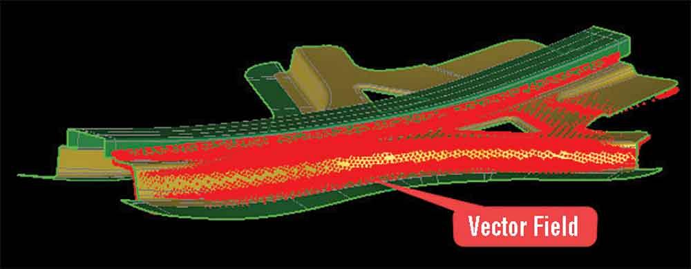
Compensation Strategy. Springback progression from one station to the next confirmed that the final form and flange die should be the target of compensation. The compensation scheme and compensation vector field used are shown in Figure 10.
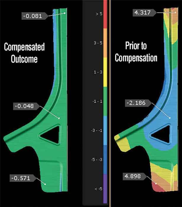
Compensation was iterated four times to arrive at a dimensionally compliant outcome (see Figure 11).
While the compensation outcome appears compliant, on a one-off basis, it is important to validate that the compensated process is in control and therefore capable of repeatable outcomes. This is an important validation to carry out before signing off on the release of engineered die surfaces for machining.
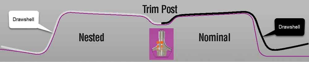
Figure 4
Machining the trim die surfaces to nest the drawshell can minimize the crushing of the panel.
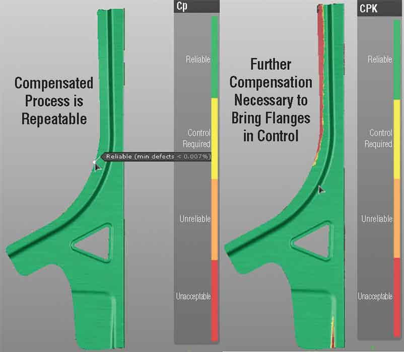
In this study, the post-compensation springback outcomes do turn out to be repeatable, based on Cp. However, small areas on the flange surface are outside of the panel’s compliance/specification limits of ±0.5 mm; this is characterized using Cpk, which is the potential of process outcomes to meet specifications in a repeatable fashion (see Figure 12).
In this case where the process is confirmed to be repeatable (good Cp) but not entirely compliant (inadequate Cpk), countermeasures may include additional compensation, a change to how the panel is fixtured, a change to the compensation strategy, or, in the worst case, concessions on specification limits.
For this extended and diligent engineering process to pay off in the physical world—reduced tryout cycles, improved panel quality, reduced overall cost—it is imperative that tooling is built exactly as validated and that the process is run exactly as engineered!
Kidambi Kannan is technical manager for AutoForm Engineering USA Inc., kidambi.kannan@autoform.com


The Fabricator is North America's leading magazine for the metal forming and fabricating industry. The magazine delivers the news, technical articles, and case histories that enable fabricators to do their jobs more efficiently. The Fabricator has served the industry since 1970.
start your free subscription
Easily access valuable industry resources now with full access to the digital edition of The Fabricator.

Easily access valuable industry resources now with full access to the digital edition of The Welder.

Easily access valuable industry resources now with full access to the digital edition of The Tube and Pipe Journal.

Easily access valuable industry resources now with full access to the digital edition of The Fabricator en Español.
In this episode of The Fabricator Podcast, Caleb Chamberlain, co-founder and CEO of OSH Cut, discusses his company’s...


