


Diemaker/Developer
It is best to have the last part and last strip available for inspection when the tool goes in for maintenance.
What is “milk run” maintenance? It is basically a phrase to describe the regular maintenance of the tools and dies used to produce parts needed. To keep inventory levels in check and pipeline activity at an even keel, they usually are done on a weekly or biweekly basis.
You should be able to count on a die that has been maintained to go in and make good parts.
A few practices may help streamline the process of readying your steady revenue generators—stamping dies!
1. Have Spares on Hand. On high runners—dies made to last for high-volume, long runs—you should have a predetermined number of ready-to-plug-in spares. (Hopefully you considered these during the quoting process and then finalized how many you would need during the design phase.)
2. Sharpen Consumables Constantly. Consumables (cutting components, mainly) usually are sharpened, shimmed, and put back into the tool each cycle. On larger, more complex tools, it is possible to run into a lead-time crunch while you are performing maintenance between runs. When this is the case, take a cue from the pressroom single-minute exchange of die (SMED) team and perform some of the work ahead of time.
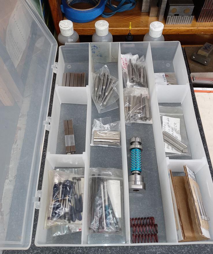
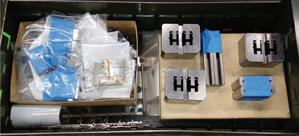
One way you can do this is to create a dedicated, compartmentalized drawer—one for upper details, one for lower—that contains every component requiring maintenance at every interval. Each compartment would contain a sharpened detail with proper edge conditioning and shim size.
This is also a great way to train apprentices and junior diemakers. While the die is running in the press, they could perform the initial grinding on these tools. Theoretically, the same shim would be selected, and the same amount of material should be removed each time. Then the apprentices and junior diemakers can work with the veteran diemaker on edge conditioning and finalizing the kit. This way, when the tool comes into the shop, press downtime is reduced to a clean-inspect-swap, details-and-go situation.
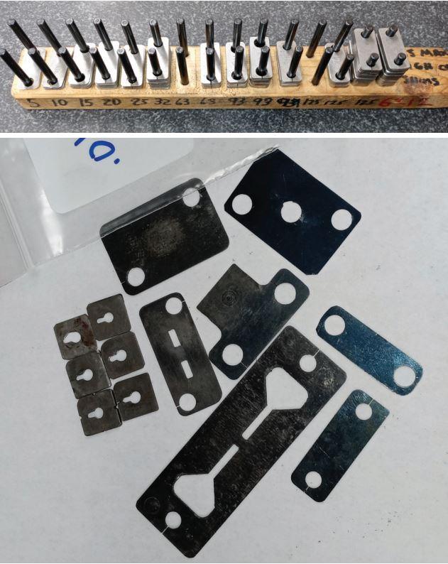
3. Save the Last Part, Last Strip. It is best to have the last part and last strip available for inspection when the tool goes in for maintenance. These can be very handy when determining if any extra actions may be needed during the procedure. Occasionally, material properties at the edge of spec or cutting lubricant that was not applied to the strip properly during the last run—or a host of other reasons—can cause wear or galling that is not addressed by the standard operating procedures (SOP). (This is why the word theoretically is added regarding the standard material removal amount!)
4. Circulate Inspection Report. You can take step three even further by providing the last inspection report to the diemaker when the die goes into the shop. These documents usually monitor critical-to-quality (CTQ) specs and dimensions that need to be controlled for internal purposes. For example, the part may need to fit into a fixture properly in a downstream assembly operation. This is not meant to create a knee-jerk reaction in the die shop. A dimensional problem during the last run may have been human-induced or some sort of random occurrence.
Die degradation may occur right before our very eyes, but so gradually that you don’t pick up on it. The inspection report helps you to watch for trends so that you can make the proper correction before a first piece is rejected during startup of a run.
On high-volume, long-runs dies, you should have ready-to-plug-in spares on hand.
Usually, dimensional creep does not occur on the parts receiving constant attention. Things such as wear plates on thrust-controlling members, stripper guides, leader pins, bushings, gibs on the press slide, and a multitude of other components not on the routine maintenance calendar can slowly degrade and eventually cause problems.
5. Take Note of Total Hits. Even tools that were dialed-in can fail during a run every now and then. It happens! Your ERP system tracks everything right down to cups available at the water cooler! So, when an unexpected breakdown occurs, take note of the total hits on the die in your tool log. This data can be used in the shop to swap the component next time before failure occurs. The data should also be fed back to engineering to fortify your lessons-learned log or predictive maintenance program. (This is a subject all of its own.)
A couple of simple tricks can save time while not sacrificing quality.
6. Shim Pack Arrangement. Instead of organizing the shims by insert or punch, organize them by thickness. Create one package containing every size of shim for that particular component. For example, a 0.005-in.-thick shim package would contain a 0.005-in.-thick shim for every die insert in the tool. There would be packages for each shim thickness and each tool component, top and bottom. The interval between shim thicknesses would be determined by the engineering department, for the most part. These would be based on type, temper, raw material thickness, and tool steel selection that the die components are made from.
7. Double-end Cutting Punches. If you stop to look, there are many symmetrical cutting punches. When it makes sense, add a screw hole to each end and flip the punch after completing the first cycle. After both ends are used once, sharpen and shim appropriately. The same shim thickness should work for both ends. If the punches are heeled, you could mill a clearance into the punch holder or backup plate during the build. On sheared punches, the floor could be “3D” milled to accept the shape of the footprint, using modern equipment and programming software. (OK, double-end rooftop punches may not be a fit for all situations!)
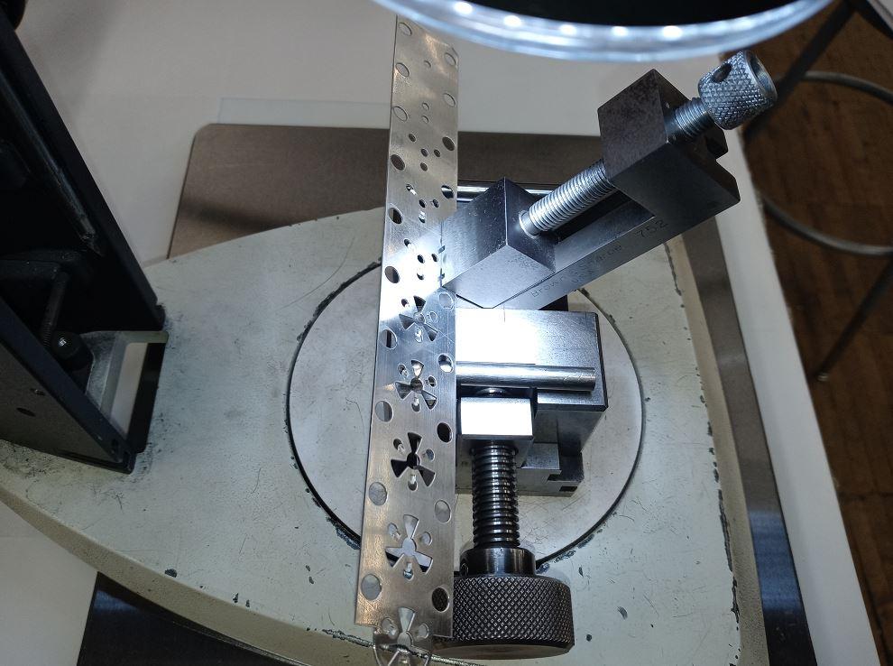
8. Wear Indicators. Where possible, add a precisely machined line into wear components. The depth of the line should be precise. This helps detect wear plate degradation that could cause a part problem. If the maximum acceptable wear on a wear plate is 0.004 in., you would machine a 0.003-in.-deep X into the plate. Then, the wear taking place will be visible as the line gets thinner during stamping. When you start seeing portions of the line disappear, maximum allowable wear has occurred, and it is time to replace or resurface and shim the plate. Also, you can use the X shape to see if there are any uneven or abnormal wear patterns. If this occurs, you should resurface the subcomponent holding the plate properly. You can apply this to pins and bushings also.
Feel free to utilize all the good tips and tricks to keep your tools and dies in tiptop shape, but do not take shortcuts! If you are not at the stage of kitting the components and the actual maintenance is performed while the die is out, you still need to follow the SOP. Do not fall for the temptation of letting go a component that “looks good enough!” Once a detail wears to a certain point, further use brings on rapid degradation, which likely will result in failure or a part spec that is out of tolerance during the next run.


The Fabricator is North America's leading magazine for the metal forming and fabricating industry. The magazine delivers the news, technical articles, and case histories that enable fabricators to do their jobs more efficiently. The Fabricator has served the industry since 1970.
start your free subscription
Easily access valuable industry resources now with full access to the digital edition of The Fabricator.

Easily access valuable industry resources now with full access to the digital edition of The Welder.

Easily access valuable industry resources now with full access to the digital edition of The Tube and Pipe Journal.

Easily access valuable industry resources now with full access to the digital edition of The Fabricator en Español.
In this episode of The Fabricator Podcast, Caleb Chamberlain, co-founder and CEO of OSH Cut, discusses his company’s...


