


Contributing Writer
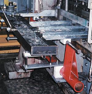 |
| Figure 1 Scrap is removed under the die and a tray moves it to a bin. |
However, if scrap is not removed from the press in an efficient manner, the cost per part produced increases.
How a company chooses to implement new processes can play a large role in where it will be in years to come. If a stamper wants to expand the business, how scrap is handled can impact the bottom line and production efficiency. Prospective customers would rather see operators checking parts than standing in front of a press watching it go up and down and clearing scrap manually.
Regardless which scrap removal system best suits a stamper's operation, process, people, and budget are the primary factors to consider for each option. Following is an overview of some of those options.
Years ago it was common practice to move slugs from under dies by clamping an air line onto the bolster and blasting it with air. This removed not only the slug but also any oil that was on the bolster, creating an airborne mist throughout the plant.
If air will be used, it should be controlled with air solenoids that are programmed with the press controls, which can coordinate short bursts as needed. The noise level can become high if several units are in operation at the same time.
Air shakers and transporters have a bore within them like an air cylinder. They have either a bumper or valving that changes their motion enough to cause anything on the trays in which they are driving to go one way. They simulate the "tablecloth effect" by pulling the tray from under material and causing it to move forward.
This type of scrap removal requires frequent filling of the lubricator, sometimes daily. The equipment is portable, fits in small areas, and is suitable for use with smaller presses.
The weight of the trays -- both total weight and weight distribution -- determines what size press these units can be used on. The total weight of trays driven by an air shaker cannot exceed the manufacturer's rated weight capacity. Also, the trays must be balanced to prevent side loading on the guiding mechanism of the shaker unit (see Figure 1). For installations that have too much tray weight, multiple shaker units can be installed to stay within the manufacturer's capacity limits.
Different tray sizes must be attached for different-sized jobs.
A rigid tray material can be used to overcome the effects of using a heavy oil lubricant. The material looks like pebbled steel with a texture that has peaks and valleys. The scrap slides on the peaks while the oil flows in the valleys.
The more care and time given to the installation of the system, such as extra guiding for trays, the better the result. Shakers that are permanently mounted with proper tray support or balancing can be durable. Reliability varies depending on the application, such as when systems are removed and installed for die changes.
Typically, seals and guides must be rebuilt if they are used for operations not intended by the manufacturer.
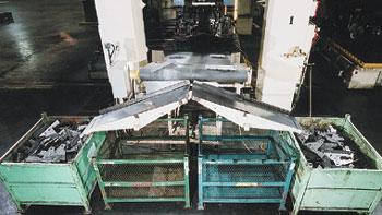 |
| Figure 2 A belt conveyor removes finished parts from the ends of the press to part boxes or pack |
Most belt conveyors are designed to handle parts that are uniform in shape and large enough to avoid getting caught under the edge of the belt. These conveyors are well-suited for removing finished parts from the ends of the press to part boxes or packers (see Figure 2). They should be set up with two boxes for running a single part so that the press does not need to shut down while waiting for a lift truck to bring an empty container.
Some manufacturers specifically design small conveyors for scrap removal under dies. They feature a low profile for more clearance of scrap, side guides to reduce the amount of scrap that gets under the belt, and quick-belt-change systems.
The shape, size, and sharpness of the scrap must be considered when selecting a conveyor type and belt. Conveyors should be stored away from traffic areas when not in use to reduce the risk of damage.
Belt conveyors can be driven by air power, electricity, or hydraulic power. Two people usually can move them from one press to another. Although fixed in size, these conveyors can be adapted for width with the addition of deflectors. They can be used to remove material on an incline, if required; the angle of incline can be increased with the addition of cleats to the surface of the belt.
Sometimes slugs do not fall off a conveyor belt but instead go around the pulley, causing them to carry over onto the bottom side of the belt. Smaller pulleys are less likely to carry over scrap because of the smaller roller diameter and the decreased traction force to keep the belt moving. The use of heavy stamping lubricant will increase the amount of carryover on the belt.
Belt replacement usually is required if the belt is torn or ripped.
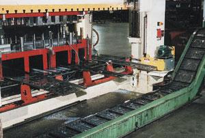 |
| Figure 3 Hinge belt conveyors are rugged conveyors that use steel plates with built-in hinges between the plates. These types of conveyors are well-suited for elevating material into hoppers above floor level because large cleats are welded to the belt |
Hinge belt conveyors are rugged conveyors that use steel plates with built-in hinges between the plates (see Figure 3). They use a positive drive system with a roller chain, which is part of the belt system. The pin in the roller chain is the same pin that goes through the hinge. Side wings typically protect the chain, which keeps the scrap from getting into the chain rollers.
The conveyor should be wide enough to keep the scrap away from the side wings, because this is where damage will occur in the transitions from flat to inclined sections. These are well-suited for elevating material into hoppers such as trailer or lugger bins above floor level, because large cleats are welded to the belt. They also are commonly used in pit applications and are stationary because of their weight.
The most common hinge belt pitches (the distance from the center of one hinge to the next) are 1.5, 2.5, 4, 6, 9, and 12 in., with the largest pitches available in widths up to 144 in.
Vibratory trough conveyors typically are used for horizontal movement of material. They move material by causing it to make small jumps along the tray. An eccentric, which moves the tray upward in an angular motion, causes the product to be thrown slightly ahead, and this movement can be repeated several hundred times per minute.
The trays are supported by various means, such as rubber elements or fiberglass leaf springs. The advantage with the tray is that there is no belt to get damaged. These can be used under presses or floor-mounted for moving material horizontally and then dumping it into an incline conveyor for filling hoppers.
Because these conveyors use trays, no material carries over, keeping the pit or floor clean. The vibration of the material does create some noise.
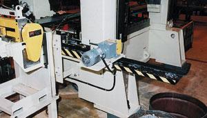 |
| Figure 4 The shuffle drive creates a motion in the tray similar to the tablecloth effect to move scrap in the desired direction to a scrap bin. |
These heavy-duty shuffle drive systems can be press-mounted for scrap removal from under the dies or floor-mounted for pit applications. The shuffle drive creates a motion in the tray similar to the tablecloth effect to move scrap in the desired direction (see Figure 4). They typically are used on presses with capacities higher than 150 tons.
These motor-driven gearboxes move the tray back and forth at about 70 strokes per minute (SPM). Only one is required per press, and it is usually mounted on the column, transmitting its motion across the press with a pivoting cross shaft. These systems are designed to become part of the press and usually are not portable. Their operation is quiet.
During die changes, the trays are lifted up from the cross shaft; when the next die is placed on the bolster, the appropriate trays slide in between parallels and sit on the cross shaft
Parts can run out the back or front of the press with the same drive. The system also is well-suited to presses with rolling bolsters. As a common unit they may be mounted on the press and can operate both bolsters when they are in operating position.
Because only the tray is in the area of slug removal, the conveyor can have a very low profile. The shuffle drive also can be used for pit conveyors or floor-mounted systems because it is a horizontal-motion handling system and can transmit the motion several hundred feet with only one drive. Trays are self-cleaning as they slide the material along, with no oil or scrap carryover, which keeps the work area cleaner.
Magnetic conveyors can be used for applications involving ferrous materials. Typically, a magnetic conveyor has a belt with magnets mounted to it and moves under a sheet of stainless steel. When the tray comes to the end, the belt with the magnets turns away from the stainless sheet, causing the material to fall. For safety, most moving parts are within the frame of the conveyor.
These conveyors can move material vertically and even upside down if the weight of the product allows it. By design, they do not have a low profile and cannot be moved around manually during die changes.
A gravity system is a good tool when used properly and when designed far enough ahead to suit the product range. In this type of system, a hole in the bolster allows scrap to fall onto a pit-mounted or floor-mounted conveyor. The hole in the bolster weakens die support, so some companies have changed back to solid bolsters, moving the scrap to the back or front of the press and dropping it into the pit.
An advantage of the gravity system is that during die changes, nothing needs to be added or removed from the press for scrap removal, which saves time.
Gravity also can be used to shed the scrap off the front or back of the press if the shut height is high enough to allow for this. Again, the scrap can go into bins or a pit conveyor under the press. Care must be taken to ensure scrap does not get caught in the scrap chutes and plug the opening.
In-floor systems reduce forklift traffic and mess on the shop floor. The pits must be designed to ensure easy access for maintenance. Pits also should have a drop from one end to the other to allow tramp oil to gather in a sump for filtering or disposal. The pits should be lined to ensure that no contaminants enter the soil.
In-floor systems can be under the press or at the end of the press, with heavy floor plates on top to allow for lift truck traffic to pass over.
Typically, hinge belt and trough conveyors are used with in-floor systems.
The key factor in selecting a scrap removal system is that it must increase press uptime by reducing setup and maintenance time. A system that is inadequate for the process or is installed in an area that is not easily reached for maintenance can only add to production downtime.
Paul Tamlin is president of Press Room Techniques Inc., 103 Blackbird Road, Lindsay, ON K9V 4R1, Canada, phone 705-374-5225, fax 705-374-5069, ptamlin@lindsaycomp.on.ca, www.pressroomtechniques.com. Press Room Techniques Inc. manufactures scrap and part removal systems.


The Fabricator is North America's leading magazine for the metal forming and fabricating industry. The magazine delivers the news, technical articles, and case histories that enable fabricators to do their jobs more efficiently. The Fabricator has served the industry since 1970.
start your free subscription
Easily access valuable industry resources now with full access to the digital edition of The Fabricator.

Easily access valuable industry resources now with full access to the digital edition of The Welder.

Easily access valuable industry resources now with full access to the digital edition of The Tube and Pipe Journal.

Easily access valuable industry resources now with full access to the digital edition of The Fabricator en Español.
In this episode of The Fabricator Podcast, Caleb Chamberlain, co-founder and CEO of OSH Cut, discusses his company’s...


