


President
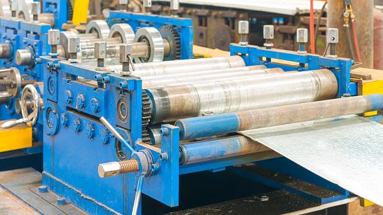
Sheet metal is processed through rollers at a steel plant. gjp3111/iStock/Getty Images Plus
When trying to determine the source of splits and wrinkles in their formed components, metal stampers often forget about anisotropy. Also known as directionality, anisotropy is a change in the crystalline structure of metals during the rolling process. Both cold- and hot-formed coils are subject to anisotropy from the intense force of the rolling operation. As a result, the mechanical properties can be significantly different at different directions across the plane of the sheet material.
Just a few months ago I had a conversation with a diemaker over coffee. He shared his frustration over the volume of splits he experienced on a particular component and detailed the troubleshooting efforts that failed to determine the cause. I suggested he try rotating the blanks.
I encountered him again a few weeks later, and he was ecstatic that simply rotating the lifts eliminated the splitting issues. But I was surprised that even though he knew his blanks were anistropic, he’d never considered that to be a possible cause of the problem.
Rolling in a mill moves the metal through a series of counterrotating rollers above and below the metal. The rollers introduce bulk plastic deformation to the metal to form it to the desired dimensional thickness (see Figure 1). Deformation changes the microstructure of the metal by changing the size of the crystal grains and introduces an orientation based on the direction and the force used in the deformation.
During deformation, the grains can both elongate and rotate. The crystals align based on the direction of the stress applied by the rollers during deformation. As a result, the properties of the metal change as the direction of the component is changed. The direction of the microstructure affects mechanical properties, magnetic properties, electrical conductivity, and corrosion resistance, and this variability in properties based on direction is called anisotropy.
Labs measure anisotropy through a uniaxial tensile test. One of the conventional characteristics measured during a tensile test is vertical anisotropy, or the r-value. The r-value is a measure of the true plastic width strain of the sample compared to the true plastic thickness strain. The standards that reference plastic strain include ISO 10113, ASTM E517, and JIS Z2254.
To calculate the r-value, the lab samples a cross section of the tensile specimen and measures the sample’s deformation across both the width and the thickness. If the sample deforms more across the width, then r is greater than 1. If the sample deforms more across the thickness, then r is less than 1. If the r-value is 1, the material is isotropic, which means it demonstrates no directionality.
Tested samples with different orientations on the coil reveal the hardening behavior of the metal across two different directions on its plane, as well as the thinning behaviors when measured across the material plane. These values help determine the material’s ability to maintain its high location on the forming limit diagram to resist thinning and to reduce wrinkling.
Anisotropy can be a critical factor in both simulation and forming, and blank orientation can have a significant influence on the occurrence of splits and wrinkles in the formed material. When stampers understand and consider r-values in the simulation and design stages, they can achieve better forming results and develop a meaningful body of knowledge about good practice in preventing failure from anisotropy.
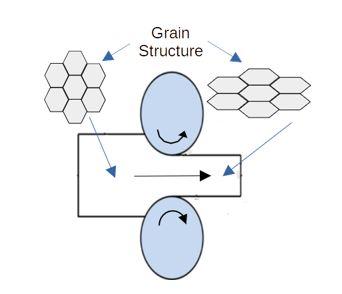
FIGURE 1 As metal moves through rollers in a rolling mill, they introduce bulk plastic deformation to the material to deform it to the desired dimensional thickness.


The Fabricator is North America's leading magazine for the metal forming and fabricating industry. The magazine delivers the news, technical articles, and case histories that enable fabricators to do their jobs more efficiently. The Fabricator has served the industry since 1970.
start your free subscription
Easily access valuable industry resources now with full access to the digital edition of The Fabricator.

Easily access valuable industry resources now with full access to the digital edition of The Welder.

Easily access valuable industry resources now with full access to the digital edition of The Tube and Pipe Journal.

Easily access valuable industry resources now with full access to the digital edition of The Fabricator en Español.
In this episode of The Fabricator Podcast, Caleb Chamberlain, co-founder and CEO of OSH Cut, discusses his company’s...


