


Welding Product Marketing Manager
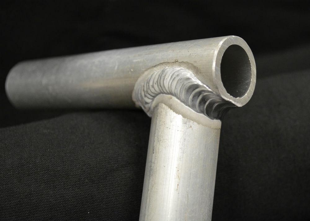
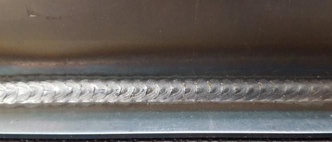
Figure 13: GMAW mixed-process control with aluminum provides ripple bead cosmetics and improved heat control. Tube saddle joint transitions from flare-bevel to T-joint with minimal melting of the tube end and cosmetics consistent with manual GTAW.
Image courtesy of Yaskawa Motoman.
All figures referenced can be viewed in the slideshow at the end of the article.
The widespread use of robotic arc welding for high-volume automotive component production has improved quality and consistency, and the implementation of gas metal arc welding (GMAW) in the fabrication process has been a significant contributor. While thin and coated materials present some challenges, welding steel is routine. Recent advances in power sources are now moving the discussion of applying arc welding robots from “Can I weld my part?” to “What do I want the weld to look like?”
The GMAW process uses a wire electrode that adds material to form the weld deposit. This not only allows a faster travel speed, but also provides a process tolerance for robotics that is maintainable at plus or minus half the wire diameter. Weld cosmetics generally are accepted as a smooth, uniform bead shape without sharply defined solidification lines.
The gas tungsten arc welding (GTAW) process uses a nonconsumable electrode to conduct the current and filler material, and typically is considered a “precision” process. The electrode is fed into the puddle externally; welders skillfully balance the melting of base material with the addition of filler material, which creates defined solidification lines and form a “ripple” in the bead. The cosmetics of the “stacked dime” or “layered penny” of the GTAW weld are aesthetically pleasing to some and are perceived as representing hand-crafted quality by others.
The capability to combine the productivity and consistency of the GMAW process with the cosmetics of GTAW weld appearance (Figure 1) has benefited aluminum welding for several years, and the recent trend of using aluminum to reduce the weight of truck trailers has deepened interest in robotic arc welding. Applying robots to these large aluminum trailer structures requires a more critical focus on the wire feed system than when welding steel.
Following are some considerations for manufacturers that have been robotically welding steel parts and now are looking to convert to or add aluminum capability.
Softer than steel, aluminum can present challenges for feeding the wire electrode. A steel system normally consists of a single wire feeder, often mounted on the robot arm, that pulls wire from a drum or spool and pushes it through the torch to the arc. Advancements in through-arm robots have helped reduce several problems that plagued wire feeding by reducing the torch length and limiting the bend radius of torch cables at the wrist. Welding with a push-only feeder on a through-arm robot today is an improvement over traditional 6-axis robots used several years ago.
Industry practice recommends push/pull feed systems for more reliable wire feeding with aluminum wire. While a wire drive system located in the torch can help pull the wire through the torch and push it the short distance through the gun barrel into the arc, a second feeder normally is placed in the system to help pull wire off the delivery package and push it to the pull torch.
Motor technology advancements have led to lighter and more compact pull torches with quick response. Not only are pull torches helping the wire feed, power source manufacturers are dynamically advancing, stopping, or even reversing the wire feed at the torch to manipulate the weld process (arc and weld puddle). A robot with a short feed distance may be able to use a pull torch only, even if pulling from a bulk wire drum.
Truck trailer manufacturers, which need long-reach robots and longer feed distances, are advised to use assist feeders in the system. If the robot is on a transport track, the wire drum is placed on the track with the robot to shorten the distance (Figure 2). Generally, a 1/16-in.-dia. electrode is not problematic to feed, and a 3/64-in.-dia. 5000-series wire is straightforward. The push/pull debate is when the softer 3/64-in.-dia. 4000-series is used. Added process capability from a high-performance pull gun makes this debate moot and eliminates the need to use small-diameter electrodes.
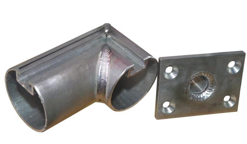
Figure 1: GMAW welds with GTAW cosmetics or ripple beads.
Image courtesy of Yaskawa Motoman.
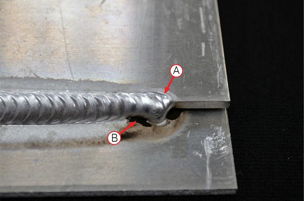
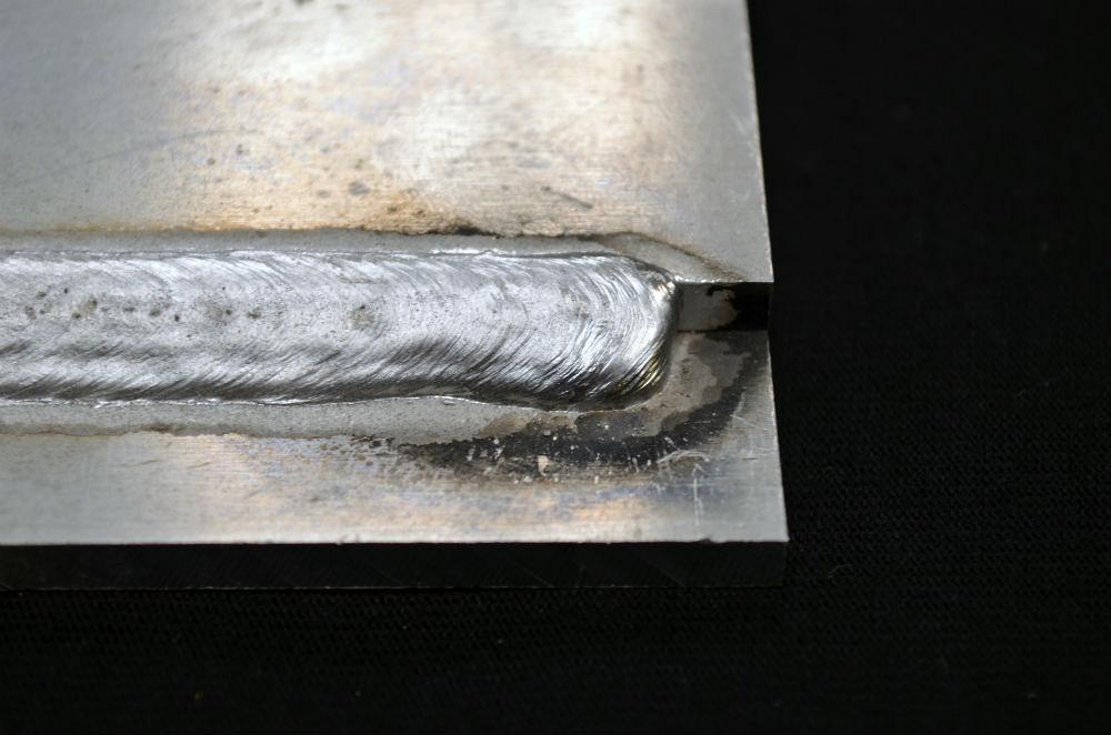
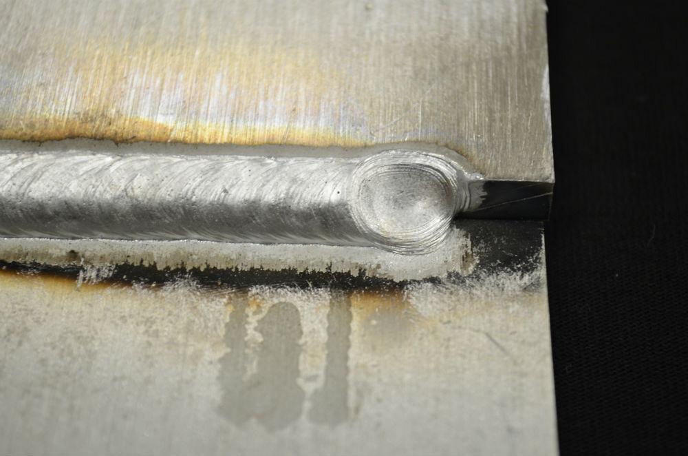
There are process differences between welding steel and aluminum. Aluminum has a lower melting point, and the weld puddle is more fluid. Pulse welding is preferred to melt the electrode with less average heat input. Because of its high thermal conductivity, aluminum requires more heat in the arc start for weld fuse-in. At the same time, its low melting point means that once heated, the weld puddle flows quickly and favors thicker sections, while thinner sections may melt through. The ability to use different weld settings to start the weld and even taper weld settings over a robot’s travel distance can be advantageous for welding aluminum and not necessary when welding steel. Figures 3 and 4 represent a poor and good arc start, respectively.
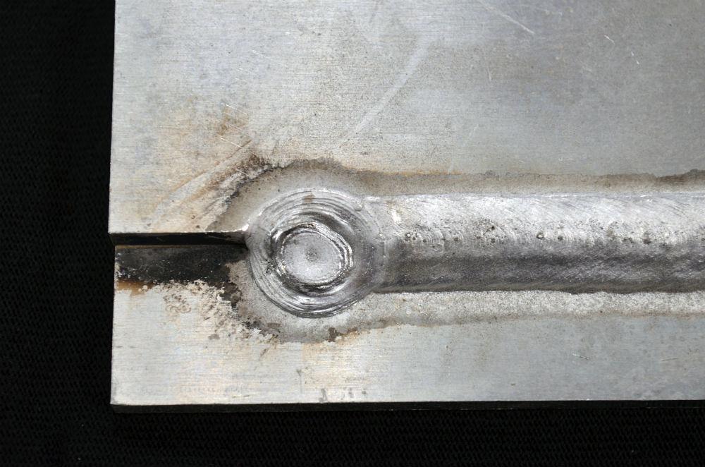
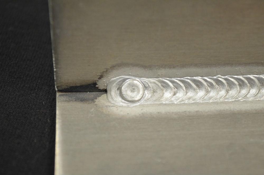
In addition to varying settings at the arc start, an aluminum weld can benefit from using multiple settings at the arc end. Aluminum solidifies very quickly, and this can leave a depression in the weld crater if the arc is turned off (Figure 5). A two-stage arc-off sequence can be used to produce a step in which the welding current is reduced to fill the puddle, then current is further reduced (less than 100 amps) to fill the smaller depression (Figure 6).
A third option is to “back step” the crater—the robot motion is reversed at the end so that the crater is not located in the weld end (Figure 7). This is used at the end to reduce weld size variation that might create a stress riser if subject to fatigue loading.
These two-stage starts and crater ends that enhance the cosmetics of aluminum welds take longer to process compared to welding steel. It is common to allow for 1 to 1.5 seconds for aluminum start and end, while steel is less than 0.5 second total for both start and end. The good news is that the faster solidification rate of aluminum results in faster travel speeds than a similar weld size on steel. It is common to use a steeper push angle of 10-15 degrees for aluminum to flatten the bead versus 5-10 degrees for steel.
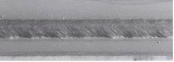
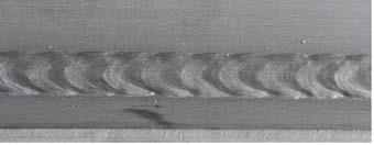
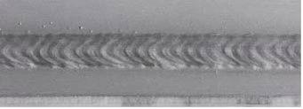
While pulse welding normally is used with aluminum, a process variation has been used to alternate between dual settings of a high and low current to produce ripples in the weld bead. The faster solidification rate in aluminum makes the ripples more distinct, as the higher settings create a wide puddle and the lower settings reduce the size, creating a space before the next large puddle. The change between weld settings normally is 2 to 5 Hz, with the frequency controlling the spacing between the ripples. Changing the difference between the high and low heat settings controls the size of the ripples; a greater difference between high and low creates larger ripples with smaller spaces in between (Figures 8-10).
While the bead appearance may be more appealing, there is a secondary benefit of controlling the heat input into the part. Because of the high thermal conductivity of aluminum, it is possible for the heat from the weld to exceed the travel speed, which causes the bead to get wider and possibly even burn through. Robots have the ability to taper weld parameters over distance, so the wire feed speed can be reduced proportionally while traveling to help compensate for this. However, alternating between high and low weld settings provides a cooling period, which helps to balance heat input and normally eliminates the need to vary parameters during the weld.
While the GMAW-created ripple bead appears to have the cosmetics of a GTAW weld, it is not replicating the precision normally associated with this process. Robots can be used to perform GTAW (Figure 11), but there often are special considerations:
Manufacturers that implement robotic GTAW generally are not trying to reproduce the ripple bead cosmetics; instead, they are interested in reducing the bead size. The objective is to reduce secondary operations related to finishing. Some examples are using GTAW without filler to melt corners on an appliance so it can be painted without grinding or welding an automotive manifold port with a process that will not produce spatter that may damage the engine.
Some customers may desire the ripple bead cosmetics for steel products such as recreational vehicles and sports equipment. With aluminum, creating this effect requires only a small change in heat input between the high and low settings. A change of 50 percent produces pronounced ripples, yet the weld parameters still provide arc stability between the two settings. A steel weld puddle will not solidify enough to produce a ripple.
Newer weld process capability now can be used to produce ripple bead cosmetics in steel (Figure 12), which is accomplished by not only alternating between high and low, but changing processes during these times. This ability to mix processes means that a pulse welding process could be used during the high-current period, and a short-circuiting process could be used during a lower setting.
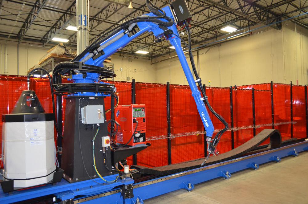
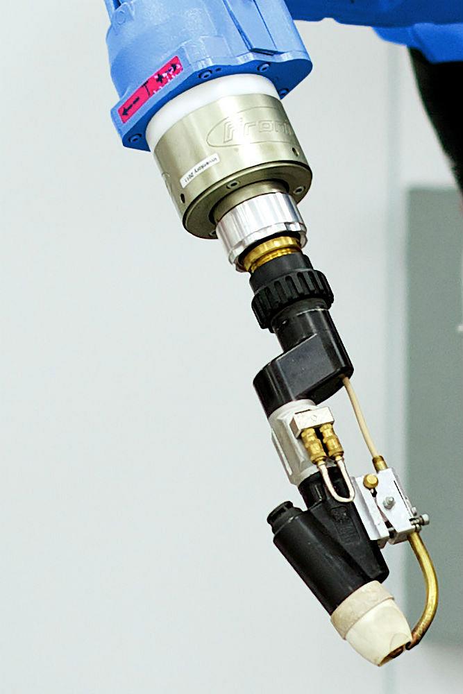
Figure 2: Extended reach robot on servo track; features push-pull feed and bulk wire drum on carriage.
Image courtesy of Yaskawa Motoman.
Advancements in power source process control allow an arc to be extinguished between short-circuit periods and then re-established with very minimal spatter. This ability to increase the variation between high and low settings, while maintaining arc stability, now allows the steel weld pool to solidify and produce a ripple. The same principle applies with heat or process settings that control the ripple size and frequency of process changes, regulating the ripple spacing.
The mixed process control brings benefits for aluminum welding as well, because more precise heat control can produce the ripples and reduce unwanted melting of surrounding base material (Figure 13).
A GTAW weld produced by a skilled manual welder is beautiful and should be admired. While a manual welder provides a level of real-time feedback to part variation and process adjustments that cannot be copied by automation, the current shortage of skilled labor and increasing pressure to reduce costs are leading more industries and smaller manufacturers to implement robotic welding. Process advancements continue to develop and allow automotive manufacturers to weld faster. These innovative enhancements also enable manufacturers to tailor the look of each weld.


The Fabricator is North America's leading magazine for the metal forming and fabricating industry. The magazine delivers the news, technical articles, and case histories that enable fabricators to do their jobs more efficiently. The Fabricator has served the industry since 1970.
start your free subscription
Easily access valuable industry resources now with full access to the digital edition of The Fabricator.

Easily access valuable industry resources now with full access to the digital edition of The Welder.

Easily access valuable industry resources now with full access to the digital edition of The Tube and Pipe Journal.

Easily access valuable industry resources now with full access to the digital edition of The Fabricator en Español.
In this episode of The Fabricator Podcast, Caleb Chamberlain, co-founder and CEO of OSH Cut, discusses his company’s...


