


Welding Instructor
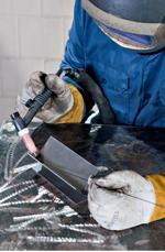
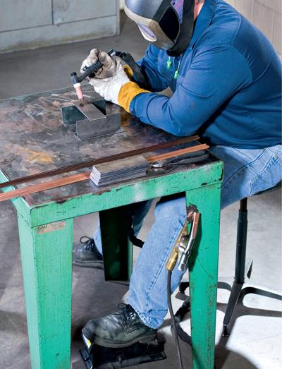
Figure 1: GTAW requires concentration. For this T-joint, the welder starts by getting comfortable, positioning the filler rod, and keeping his hands near the end of the torch handle, far away from the heat of the arc.
Watch a welder in action and you quickly understand why gas tungsten arc welding requires so much skill. The nonconsumable tungsten electrode must be prepared and inserted into the torch just so, and shielding gas must be set low enough to avoid excessive weld pool turbulence, but still high enough to adequately shield the weld from the atmosphere. The welder sets amperage at the power source, tweaks amperage levels in-process with a foot pedal, feeds wire manually, and travels at just the right speed to lay down what often is a cosmetically important weld joint that also must meet stringent welding standards.
With so many things going on at once, GTAW is a little like juggling while riding a unicycle. With practice, the welder’s eye, arm, hand, and foot coordination will improve.
To master these skills, it may help to analyze common defects that can slip into a weld joint. Quite often gas tungsten arc welders work with high-quality, expensive material, which can make any melt-through a costly defect. This is why it’s common for companies to keep the amperage settings constant—per the welding procedure specification (WPS)—and therefore do not give the operator access to a variable-amperage control, like a foot pedal. Welders still must work their torch position and be right on the money with their speed to produce an optimal weld. In job shops and other operations with high product mixes, the welder will change the machine’s amperage setting for each job, depending on the material, thickness, and joint geometry involved.
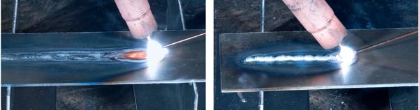
The optimal amperage setting doesn’t help much, though, if the welder does not ensure adequate melting of both the filler and base metal. Fearful of melting through, beginners often dip the filler rod into the arc zone, watch the filler melt, then immediately move the torch along the weld joint. In these cases, welders probably melt the filler but not the base metal, causing incomplete fusion—a severe discontinuity that virtually guarantees the weld won’t pass muster.
Experienced welders know that, for many GTAW applications, they walk a tightrope between melt-through and incomplete fusion. To find the sweet spot, where the heat is not too high or too low, they must concentrate and manage many variables (see Figure 1).
The nonconsumable tungsten electrode really defines GTAW, and welders must prepare them properly. For direct-current welding, a tungsten tip ground to a needlelike shape with a long taper (for example, 20-degree grind angle and greater included angle) produces a wide arc, while a tungsten ground to a shallow angle (for example, 60-degree grind angle and lesser included angle) produces a narrow arc (see Figure 2).
A wide arc spreads the arc zone, while a narrow arc provides a much smaller fusion area. Depending on the joint geometry and thickness, a narrow arc may require the welder to sweep the torch across the joint a bit more, or risk missing areas and causing incomplete fusion, although a sharp pointed tungsten has a wider arc and does provide better directional control of that arc. When the welder moves the molten pool across the joint, even in a tight root, a long taper probably will perform better than a blunt end.
A sharp point works best for thin metal, for which melt-through usually is more of a problem than incomplete fusion, and working at lower amperages will allow the tip to stay sharp. At higher amperages, the very end of a sharp tungsten tip can be blown off, so many welders will grind a flat spot (land) on the end of the tip to prevent tungsten inclusions.
Using alternating current can change how the welder prepares tungsten, depending on the type of power source used. Modern inverters produce an AC arc that allows a sharp, pointed tungsten to remain relatively sharp even through the electrode positive side of the AC wave cycle. With transformer-rectifier power sources, some amount of tungsten “balling” is likely to occur. Balling describes when the end of the tungsten electrode becomes rounded due to the heat produced with AC (primarily from electrode positive). Many welders will ball the end of their tungsten on purpose with direct current electrode positive (DCEP) before switching over to do their welding with AC.
Last, welders should consider the type of tungsten used and the quality. A pure tungsten electrode will not hold its shape as well as a ceriated tungsten electrode. And not all ceriated tungsten electrodes are created equal. Brands that cost a little more are generally of a higher quality because of the way they have been manufactured and so will perform better that the lower-cost, lower-quality electrodes.
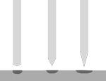
Figure 2: For GTAW in direct-current electrode negative (DCEN), a tungsten with a greater grind angle (as on the far left) will produce a narrower arc, while a tungsten ground with a long taper (on the far right) will produce a wide arc with better directional control.
The amperage setting must be appropriate for the metal thickness. A thicker base metal has a quench effect. Because most GTAW operates in DCEN polarity, the process directs heat away from the torch and into the workpiece—and thick metal can dissipate that heat very quickly. The opposite applies to thin metals, which require lower amperages (see Figure 3).
Unlike other processes, GTAW allows the welder to fine-tune the amperage with a foot pedal (see Figure 4). A current reading on a GTAW power source shows the amps applied only when the foot pedal is fully depressed.
When asked how they prefer to operate the foot pedal, two experienced welders probably will give two different answers. Everybody has a unique feel for where they like to set it. For instance, one welder might like to set amperage at the power source on the high end of the range for a particular metal type, thickness, and tungsten diameter. This means that the amperage “sweet spot” usually occurs when the welder has the foot pedal depressed about a quarter of the way. This allows the process to melt the metal and form the weld pool relatively quickly, and allows the welder to travel faster. Throughout, the welder monitors the weld pool size, laying off the foot pedal slightly if he detects the pool is about to grow, and pressing the pedal slightly more when he sees the pool start to shrink.
All welders eventually discover their own “foot pedal style,” so to speak. This is just a comfortable place that gives them the most control so they can monitor the weld pool and make necessary adjustments. The trick is to make it easy to find the sweet spot, that midpoint where amperage can be adjusted equally up or down as needed.
Setting amperage so that optimal heat occurs only when the pedal is 25 percent depressed does require the welder to feed filler metal and travel quickly. Filler metal has a quenching effect on the weld, and it can take some dexterity to dip that filler into the pool at a high welding speed. If the welder doesn’t move and feed filler metal relatively quickly at a higher amperage setting, he will see the weld pool grow until it is uncontrollable, eventually melting through.
For this reason, he may prefer to set the machine so that optimal amperage will occur when the foot pedal is depressed 75 percent of the way. This allows the welder to increase heat to some extent, but also to decrease heat input considerably if necessary. For beginners, decreasing heat allows them to work at slower travel speeds and consequently have more time to add filler metal to the joint. This is a little like juggling balls on the moon, which has six times less gravity than Earth—everything moves more slowly. Still, if the welder travels too quickly at this lower amperage, he may produce a weld with incomplete fusion. In this case, incomplete fusion often occurs because traveling too quickly at a lower amperage doesn’t allow enough time to heat the base metal.
Then again, welders may prefer to set the machine so they need to depress the foot pedal fully to ensure they get enough amperage to achieve complete fusion. This essentially takes away one variable to juggle: With the foot pedal totally depressed, the amp reading on the machine theoretically is the same as what’s at the weld pool. This setup doesn’t allow the welder to increase amperage, but it does reduce the chances of melt-through, which can be a much bigger problem than a slightly slower welding speed.
Regardless of how much the pedal is depressed to achieve the optimal amperage, incomplete fusion still is possible if welders do not allow time for the arc to melt the base metal before inserting the filler rod. In this case, beginners will start the arc, insert the rod, see the filler melting, and move down the joint. Just because the filler metal has melted does not mean the base metal has. In fact, the filler metal—with its cross section almost always much smaller than the base metal’s—doesn’t take much time to melt. Simply melting it over unmelted base metal is like trying to hold the joint together with putty.
This is why, to avoid incomplete fusion, welders should wait for that base metal to melt before adding the filler wire. And if the amperage is set such that the foot pedal needs to be completely depressed, it may take a little longer for the base metal to heat up and melt. During the weld, if the welder does need to back off on the amperage, he does so only slightly. In most cases, he will probably need to keep moving the torch at a constant speed and keep his foot firmly planted on the pedal to ensure it remains completely depressed.
This setup can be ideal when welding materials like stainless, because it limits heat input. The welder reduces the chance of overheating, producing a heavy oxide layer, or, at worst, melt-through. On the other hand, gas tungsten arc welding materials like aluminum sometimes requires the welder to start the arc and then back off the pedal to prevent overheating the base metal near the end of the joint. In this case, it may be smart to set the sweet spot closer to the middle of the foot pedal’s range. (Though, again, when it comes to foot pedal usage, much of it comes down to individual preference.)
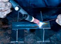
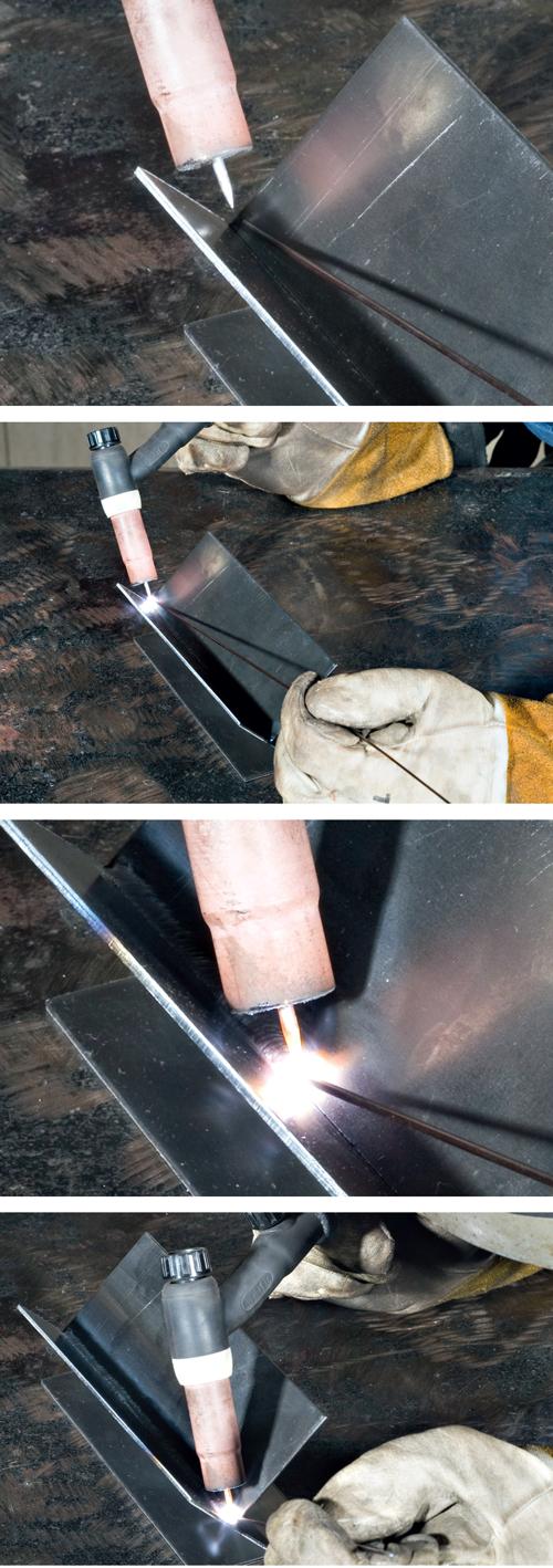
Figure 5: This incorrect torch angle directs the heat of the arc to one side, which would cause incomplete fusion on one side of a weld joint.
Polarity also affects heat input. Although most GTAW occurs in DCEN, materials such as aluminum and magnesium usually call for AC to clean the surface and remove oxides during welding, and this adds yet another variable: balancing the AC between the positive side, which provides cleaning, and the negative side, which provides penetration. Many modern power sources offer variable AC balance control, allowing welders to change the percentage of time between positive and negative to provide both good penetration and cleaning action. An excessive amount of cleaning action will limit penetration, so it may be helpful to remove heavy oxide layers before welding.
A power source with both AC balance and AC frequency controls busts up the oxide layer with a large percentage of DCEP (40 percent) and, at the same time, focuses the arc for good penetration characteristics by increasing the AC frequency (more than 120 cycles per second).
The welder may have the right amount of heat and move the torch at the appropriate speed, but all of that won’t matter if his torch angle is incorrect for the joint geometry. For butt joints in the flat position, he will want the tungsten to be 90 degrees (that is, perpendicular) to the workpiece surface. For fillet welds applied to T joints, he will want the torch angle to split the distance—45 degrees from the perpendicular section, 45 degrees from the flat section.
Beginners often have trouble with work angle (see Figure 5), and it isn’t always at the start of the weld. If a 10-in.-long weld has incomplete fusion within the last 3 in., it probably comes from work angle problems. A welder may start in the correct position and then, as he moves along the joint, change the work angle so that the torch is directing the arc to one sidewall or the other, which in turn fails to induce fusion on the opposite sidewall. This can be a greater problem with shielded metal arc (stick) welding, because as the long stick electrode melts away, it becomes easy to move it to an incorrect angle. But the problem still can arise with GTAW.
Tungsten stickout plays a role here too. The arc length—the distance between the tungsten tip and the weld pool surface—must remain as consistent as possible, often only between 1⁄16 and 1⁄32 in. (see Figure 6). The length of the tungsten stickout can depend on the joint geometry. If the welder doesn’t have enough stickout to achieve the appropriate arc length (that is, voltage) during the critical root pass, he opens the door to incomplete fusion. For proper gas shielding, the tungsten stickout shouldn’t extend past the end of the taper. This means having an assortment of cup sizes to access different joint designs and groove angles. A shorter stickout will not work in all situations, so adjustments will be necessary. The welder must be sure he can see the molten weld pool and maintain proper arc length.
The tungsten stickout should be long enough to allow welders to get in close for welding, but short enough so that an excessively long column of shielding gas doesn’t result. It doesn’t take much breeze to disturb this long column of shielding gas and expose the weld to the atmosphere. Gas lenses are a popular torch accessory that will provide better overall gas coverage and at the same time allow a much longer tungsten stickout.
GTAW requires a lower shielding gas flow rate than its wire feed counterparts. For GTAW, 15 to 20 cubic feet per hour (CFH) is common, though the exact flow rate depends on the application. A flow rate that is too high can create weld pool turbulence and cause porosity, while too-low flow rates can expose the weld to contamination from the atmosphere. Many times flow rates will vary greatly from shop to shop. It’s possible that when porosity occurs at 15 CFH, with no other changes, the porosity will clear up at 20 CFH. Drafty conditions, use of a fume extraction system, and weld position (argon is heavier that air, which can be a concern when welding overhead) are all potential reasons for a 5-CFH increase to the recommended flow rates.
GTAW has gas preflow and postflow, and the latter—the flow of gas after the weld—is particularly important to prevent discontinuities, like porosity and crater cracks. The amount of postflow needed depends on the tungsten electrode diameter. The postflow is important to both the solidifying weld pool at the end of a bead and protecting a white-hot piece of tungsten after the arc is extinguished.
Manually feeding filler metal makes GTAW a particular challenge. The trick is not to dip too much of the rod in at once. A good idea is to dip a little and dip often. Eventually welders want to be able to almost “push” the weld along. They should melt the base metal and dip the rod—not the other way around. Again, dipping the rod into the arc zone over unmelted base metal is a recipe for incomplete fusion.
When welding thinner metals, a welder can touch the filler rod to the front edge of the weld pool. With sufficient amperage, this causes the filler metal to be nearly “sucked” into the approaching body of the weld pool.
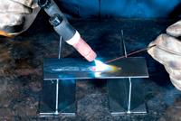
Figure 6: In this setup, the tungsten electrode is too far from the weld pool, causing the arc to spread out.
While learning, welders can try some techniques to find the right feel for the process. One way is essentially to create a kind of manual “pulse.” The amps on the machine are set so that the system produces enough amps to melt the base metal (that is, its melting point) when the foot pedal is depressed halfway. This way, the welder can melt the base metal, apply filler metal, and then lay off the pedal slightly to reduce amperage until he sees the weld solidify. Then he presses the pedal again to increase amperage, melts the subsequent base metal in the joint, applies filler, then backs off again—and so on.
This teaches beginners to identify the base metal’s melting point and to add filler material just when the base metal becomes molten. It’s a matter of learning the timing and rhythm of GTAW, and with practice, welders will increase their filler metal feed and travel and operate at a more consistent amperage.
Today’s pulsing power sources actually can be set to pulse at peak current for one second, which can have the same effect: The welder sees the metal melt, dips the rod, and sees the pool solidify between pulses. These power sources pulse much faster, of course; the pulse peaks provide penetration while the valleys between the peaks limit heat input; at, say, 500 pulses per second, the pulsing action is virtually undetectable.
Like with other welding processes, welders must consider the relationship among distance, angle, speed, and heat (DASH), and nowhere is this more critical than GTAW, which gives precise control over so many variables (see Figure 7). It’s partly because the welder can control so much—the amperage, the filler metal feed, and so on—that GTAW works so well on so many different metals.
GTAW requires concentration, but the reward is the ability to produce high-quality weld joints, including some that just could not be made any other way.

The Fabricator is North America's leading magazine for the metal forming and fabricating industry. The magazine delivers the news, technical articles, and case histories that enable fabricators to do their jobs more efficiently. The Fabricator has served the industry since 1970.
start your free subscription
Easily access valuable industry resources now with full access to the digital edition of The Fabricator.

Easily access valuable industry resources now with full access to the digital edition of The Welder.

Easily access valuable industry resources now with full access to the digital edition of The Tube and Pipe Journal.

Easily access valuable industry resources now with full access to the digital edition of The Fabricator en Español.
In this episode of The Fabricator Podcast, Caleb Chamberlain, co-founder and CEO of OSH Cut, discusses his company’s...


