


Senior Editor
Small, low-tonnage press brakes are making a comeback, and 3D-printed tools could make these machines more flexible than they already are. photo courtesy of Wilson Tool International
Small, light-tonnage press brakes, often electric or a hydraulic-electric hybrid, are undergoing a resurgence of popularity. Years ago shops might have strayed from them, considering their low tonnage and short bed lengths. After all, in a job shop, why invest in a machine that can process only small parts, while longer-bed machines can form just about whatever you throw at them?
Fiber lasers have taken cutting capacity to another level, and now shops need to do the same for forming. Offline programming and simulation can create a complicated stage-bend program in minutes, meaning an intricate part can be formed with tools spanning across the bed. Because programming is essentially automatic, these bed-spanning setups make sense even for short runs.
Considering all this, why send tiny parts to a large, extraordinarily capable machine? A staged, done-in-one setup is great, but not if the job’s sitting in queue forever, waiting for the operator to finish bending a batch of tiny brackets. In this scenario, a small electric or hybrid brake might make a world of sense. More than that, small brakes are more flexible than ever. Some come with robots that can be moved in and out as needed.
Because most of these small brakes produce only about 40 tons of forming pressure or less, they also open the door to an entirely new arena of flexibility. If a tool or specific forming aid (like guide pins, risers, or backgauges) isn’t available for one of these low-tonnage brakes, well then, why not print it?
The halls of FABTECH® 2019 in Chicago had numerous examples of how fabricators could integrate additive manufacturing into their operations. For press brake tooling, the industry seems to be taking two distinct approaches. Various vendors are selling printers that fabricators can use to print the tools themselves. For instance, Cincinnati Inc., which has been an active player in AM for some time, is moving toward 3D printers with “recipes” tailored for specific tool sets, each of which a fabricator can customize to suit.
White Bear Lake, Minn.-based Wilson Tool International has taken the second approach. The tooling supplier is doubling as an AM service bureau, working with customers to develop the best “additive” brake tool design and printing punches and dies to order.
For most, press brake tooling isn’t the first thing that comes to mind when they think about 3D printing, at least outside the metal additive arena. Fused filament fabrication (FFF) and other extrusion-based processes deposit thermoplastic polymer layer by layer, and its use continues to proliferate among prototyping and low-volume production.
Engineers might consider a non-load-bearing, low-volume plastic component a perfect candidate for 3D printing—but for a load-bearing component, not so much. That’s because many commonly printed products don’t have isotropic strength properties; strength values vary depending on the direction of force.
“When you talk about ‘additive manufacturing,’ many in the fabrication business think you’re just going to print it with a process that’s a lot like a glue gun,” said Steve Brown, press brake tooling and additive manufacturing product manager at Wilson Tool. “But there are so many different kinds of printing processes out there.”
For instance, in resin-based printing processes, light interacts with the material to convert it from a liquid to a solid. The product emerges from the liquid as a solid piece that’s very different from an FFF-printed product with thousands of microlayers.
Full-fledged goosenecks aren’t practical to print, but the industry has come up with alternative approaches. In this case, a printed tool has a relief designed for a specific return flange. photo courtesy of Cincinnati Inc.
Other additive processes can print a combination of materials. Brown described certain brake tools that require strength on the inside, mar-free bending on the outside. A nylon tool with a carbon fiber core provides both.
“[The combination of carbon fiber and nylon] is turning out to be an economical way to print a press brake tool,” Brown said. “It works really well, because you get the strength with the carbon fiber on the inside.”
Mark Watson, marketing product specialist at Cincinnati Inc., has spearheaded the company’s efforts for using Cincinnati’s small-format 3D printer in applications that aid fab shops, especially for press brake tools. “During early tests, I kept coming up with a 1-ton-per-inch limit,” he said, adding that this gives a good safety buffer for most applications that fabricators would consider printing.
He emphasized, though, that it’s ideal for fabricators to test printed tools to failure—a small investment for many printed tools. Punches and dies made of typical thermoplastic polymers have miniscule material costs. Just $20 a tool is typical.
Pushing a tool to its limits always adds a degree of unpredictability. Printed tools aren’t particularly hard, so they usually crack cleanly. “But we’re always very conservative when it comes to safety,” Watson said at the FABTECH show, holding a patent-pending printed V-die design. It had solid material under each shoulder but an open cavity in the center, with a bridge or “fuse” at the bottom of the V. Push the tool too hard, and the fuse snaps in a controlled manner. Watson added that the company has a similar design for a punch nose insert.
“Insert” is the key word. As Watson explained, fabricators with 3D printers might choose to print the entire punch or die, but this takes time. At FABTECH he showed a die that took a printer seven hours to print next to a punch that took six hours.
For a truly flexible bending environment using printed tools, Watson suggested that shops start with standard tool bases. Then, when a custom job arrives, the shop can design the exact punch tip and die geometry required. This shortens the printing time and, if the base is made of steel or another strong material, increases the tool’s overall strength.
3D-printed inserts also can work as adapters. Say an operator needs to bend cosmetically critical material; a printed insert can slip over an existing V die and serve as an alternative to a urethane drape. The insert also can serve to narrow the die opening to achieve a specific air-bent radius. In fact, one common long V die could hold two different inserts that provide two different V openings side by side.
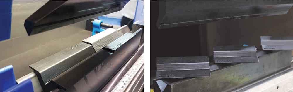
For large-radius bends, punch inserts (or entire punch tools, for that matter) can be printed to exact specs. Brown described a scenario in which a fabricator forming thin stainless or aluminum requires a 1-in. inside bend radius. To allow the material to wrap around the round punch and spring back to the desired 1-in. radius, the shop might use a round punch with a 0.625-in. or 0.750-in. radius, depending on the exact material and thickness—and it’s that “depending” that causes difficulty. An off-the-shelf punch often doesn’t result in the exact radius an application requires.
Here, a custom tool usually comes into play. As Wilson Tool’s Brown explained, there’s no reason why this round punch couldn’t be printed. Die openings in these applications usually are wide, reducing the required forming tonnage.
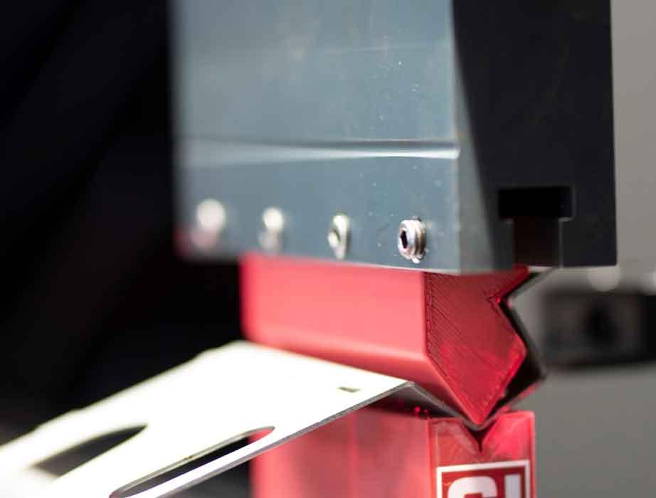
These risers were designed to allow a negative flange to clear a laser-based angle measurement device. But custom-printed risers could also help create a common-shut-height setup. photo courtesy of Cincinnati Inc.
“3D printing is a great opportunity here,” he said. “It’s a low-tonnage application. And you can print it quickly, test it quickly, and in relatively little time, get that radius just right.”
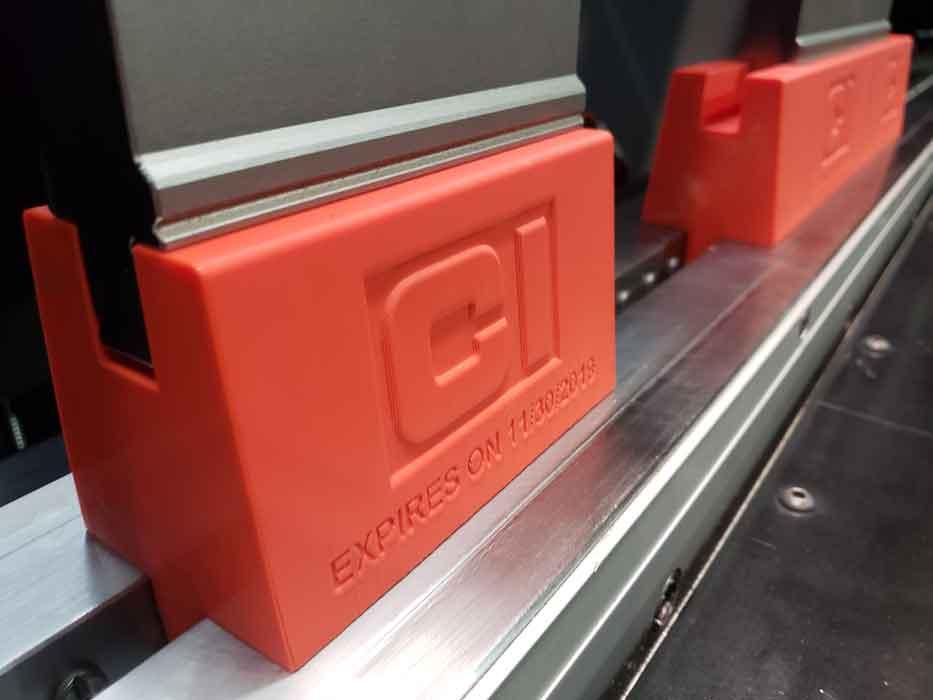
Risers also present opportunities for 3D printing. At FABTECH Cincinnati showed how printed die risers could lift the bending plane enough to give sufficient room for negative flanges to clear a laser-based angle measurement device positioned just below the tools. These risers also happened to have expiration dates printed onto them.
“Say the operator uses these risers, then removes them and puts them near a window to the outside,” Watson said. “The UV light [coming through the window] could make the printed material in these risers brittle. So I put an expiration date on them for one month. But again, it’s only $20.”
Printed custom risers could also help create common-shut-height tool sets for a staged setup. “Let’s say you have an offset die next to a V die,” Watson said, “but the right-hand station will crash unless it has a riser.” Problem is, to create a common shut height would require the riser to be 1.19 in. “Where do you find a riser that’s 1.19 in.?” Here, using 3D printing can make a world of sense.
Brown added that printed risers or die holders wouldn’t have the same precision as tool-steel holders made to machining-level tolerances. But 3D printing tolerances might be close enough, perhaps with a 0.002-in. difference between stations. “And remember, we’re not in a high-tonnage environment,” he said.
“For low-tonnage applications, these would work just fine as a die holder. You’d design the strongest tool to bottom out with no material, but if it’s only 0.002 in., you’re not going to be able to see it. And the application’s not going to care,” Brown said.
Sources conceded that 3D printing isn’t ideal for all tool geometries, particularly ones that put a lot of loading stress on the tool. If an operator needs a window punch to provide clearance for a very deep return flange, printing it probably isn’t the best idea.
The same goes for deep goosenecks. Standard goosenecks are deep so they can accept a variety of return flanges. But according to Watson, some jobs that could be bent with a standard gooseneck might not require all the clearance that gooseneck provides. In some cases, printing a punch with a slight relief—just enough clearance for the deepest return flange in a specific part—might be an efficient strategy to get a one-off or short-run job formed quickly and out the door.
Sources also conceded that tool life for any custom-printed tool won’t match the life of an equivalent steel tool. Strong printed materials show the potential for longer life, but they also cost more. Regardless, on a small press brake with low tonnage, even inexpensive printed polymers could last long enough to make business sense.
Imagine a small electric press brake with a set of standard tools, all stored conveniently in an adjacent drawer. Next to that is a set of steel bases, all of which can attach to printed dies and punches.
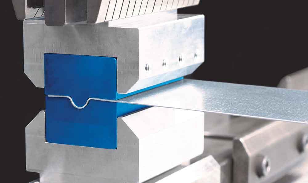
Additively manufactured die inserts help prevent part-marking and can replace urethane drape in cosmetically sensitive bending operations.
About 80% of jobs use standard punches and dies. The remaining jobs are printed, either sourced to an additive service bureau or printed in-house with a bank of 3D printers adjacent to engineering in the front office. The printers don’t take long, considering they usually need to print only a portion of a tool, not the bases. The printers also produce forming aids like check gauges, custom backgauge fingers, and pins.
These tools and aids are printed, and because most are destined for a small machine producing short bends, are usually small and light enough to slip inside a job traveler. The printed tools are exported to the brake’s bending software, which simulates the bend sequence offline and exports the program to the controller. All this has effectively made the shop’s smallest press brake its most flexible and most productive.
3D printing of brake tools is a practice in its infancy. Shops that try out a printed tool can’t draw from decades of tool design experience. In this sense, early adopters have uncovered the tip of the iceberg. The unknowns abound, but so too do the possibilities.
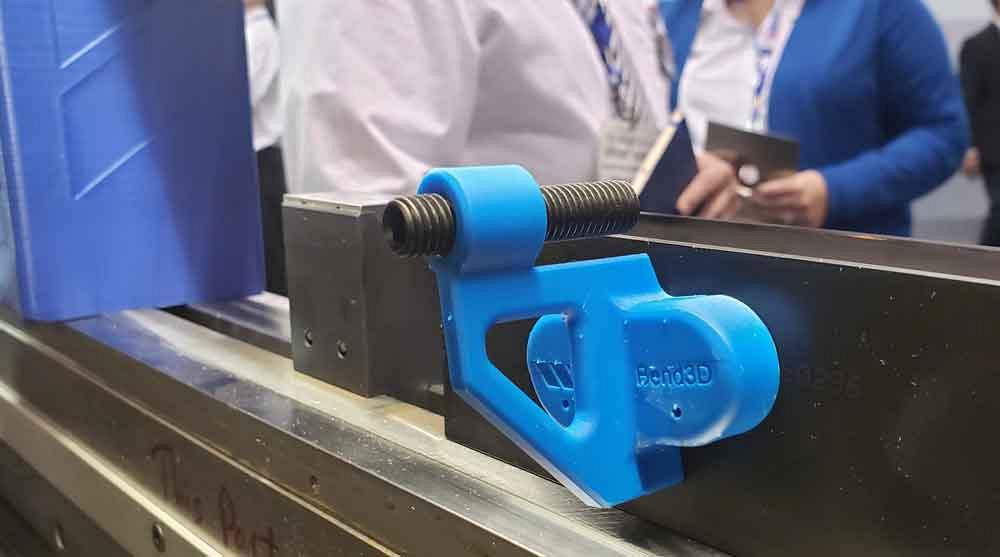
A printed backgauge, on display at Wilson’s booth, is designed for a specific family of small parts. A 3D printer also could produce custom backgauge fingers, such as those with unusual contours.


The Fabricator is North America's leading magazine for the metal forming and fabricating industry. The magazine delivers the news, technical articles, and case histories that enable fabricators to do their jobs more efficiently. The Fabricator has served the industry since 1970.
start your free subscription
Easily access valuable industry resources now with full access to the digital edition of The Fabricator.

Easily access valuable industry resources now with full access to the digital edition of The Welder.

Easily access valuable industry resources now with full access to the digital edition of The Tube and Pipe Journal.

Easily access valuable industry resources now with full access to the digital edition of The Fabricator en Español.
In this episode of The Fabricator Podcast, Caleb Chamberlain, co-founder and CEO of OSH Cut, discusses his company’s...


