


Grain direction’s effect on sheet metal bending
Why press brake operators should think twice before bending with the grain
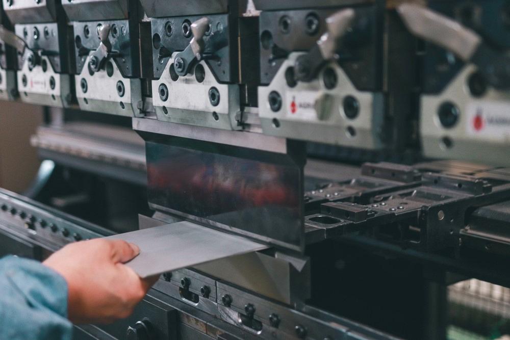
If press brake operators bend a small radius with the material grain—that is, the bend line runs parallel to the material grain direction, they should watch out for cracking. Getty Images
Question: A previous article of yours suggests that forming “with” the grain direction will manifest cracks. I might be confused over the verbiage. Does this mean the grain runs perpendicular or parallel to the bend line?
I was researching the topic because we are bending 0.060-in.-thick 3003 H14 aluminum (see Figure 1), and my toolmaker wants me to design the bends parallel to the grain, because the tool will be easier for him to work on. I’m not crazy about this idea, but I think it will be OK. Note also that this is an offset bend that will be made in a coil-fed stamping press, not a press brake, but I assume at least some of the metal forming fundamentals apply. Any further guidance on this topic would be much appreciated.
Answer: Before I delve further into this topic, I would like to begin with your comment about verbiage. Confusion over verbiage is one of the biggest problems our industry faces. This statement is true whether you are learning in the classroom or discussing a project on the job.
Very few trade-specific terms are interchangeable. One person’s bend allowance cannot be another person’s k-factor, and a k-factor is not a bend deduction—though I visit shops where this is precisely the case. Because these terms have exact meanings and applications, misusing them makes communicating complex ideas complicated and creating quality parts much harder to accomplish. Terminology misuse is often brutal to correct, and everyone will give the same response as to why they use the terms the way they do: because that’s how I learned it.
To get everyone on the same page and using the terminology correctly, I recommend posting a simple laminated wall chart or handout with all the relevant definitions. Here are a few you could include:
k-factor: A multiplier value to determine the location of the relocated neutral axis. Outside setback, or setback: The distance from the tangent point of the flat and the radius to the apex of the bend. Bend allowance: The length of the neutral axis, which can be added to the setbacks to determine the flat length of a part.Bend deduction The value that is subtracted from the total of the outside dimensions to determine the flat length of a part.Neutral axis: The theoretical area within the material at the bend that is neither expanded nor compressed.These are only a few relevant definitions; there are more. Nonetheless, when everyone is using the language correctly—well, you get the picture.
Grain Direction
Now, back to the subject at hand: the grain direction’s relationship to the bend line. In previous articles, I’ve used “bending with the grain” when the bend line is parallel to the grain direction, as shown in Figure 1. Bending “across” or “traverse” to the grain is when the bend line runs perpendicular to the grain, which makes for a stronger bend that’s less likely to crack (see Figure 2).
Bending parallel to the grain will create a weaker bend than a bend line running against or transverse to the grain. Also, the outside radius of the bend is more prone to cracking when bending parallel to the grain direction. The smaller the inside radius is when bending parallel to the grain direction, the greater the chances that cracking will occur, and the more severe that cracking can be. Using a larger bend radius can help prevent these problems.
It takes more force to bend a piece of material when the bend line runs across the grain, but that same across-the-grain bend also can hold a much smaller inside bend radius. Also, the penetration depth can change from bend to bend, depending on the bend line’s orientation to the material grain.
Not all materials have a grain direction. Copper has no grain; hot-rolled pickled and oiled (HRP&O) has some; and in mild cold-rolled steel, the grain can be quite pronounced. In stainless steel, it can be tough and sometimes impossible to define the grain and grain direction. Materials with a grain direction that affect the bend angle are considered anisotropic. Materials that don’t have this property are considered isotropic.
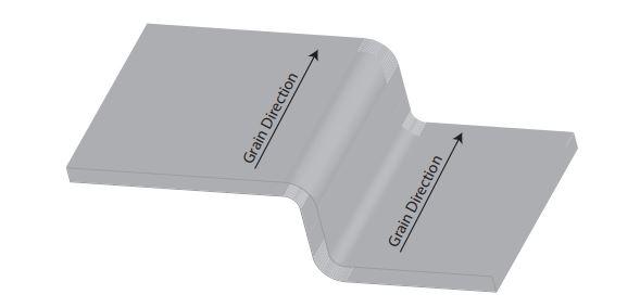
FIGURE 1. Bends made with the grain (that is, the bend line runs parallel to the grain direction) have a greater chance of cracking.
Tips to Prevent Cracking
One of the best ways to alleviate cracking is to make the inside bend radius as close to the material thickness as possible; that is, make the ratio of inside bend radius to material thickness as close to a one-to-one relationship as possible. A smaller radius pulls the material tightly around the bend and thus pulls the grains apart, manifesting as cracks. You rarely see cracks in bends where the radius is larger than the material thickness. Occasionally, the grains can be pulled apart from stretching or extending the outside radius too far. Usually, this is seen in less ductile materials or those with high tempers, such as T-6 aluminum. Nonetheless, such cracking isn’t common.
If you must bend with the grain and cracking is still a problem, you might be able to use the material in an annealed state and then temper it as needed. For example, you can form soft aluminum and then temper it to the T-6 condition.
Also consider the types of bends you’re making. Offset bends are tricky devils to start with, as the tooling constrains the center flange. This constraint leaves the elongation of the bend to go somewhere else, notably the two outside flanges. This shifting around of the elongation makes them dimensionally hard to predict. Such offsets also work best with a smaller bend radius, which adds to the cracking problem.
If you’re forming this part on a coil-fed stamping press, you’re probably bottoming (as the stamping process does not lend itself well to air forming), so the options to reduce cracking with air forming methods are not available. However, adding a little angular clearance to the die set will help maintain the parallelism between the bend flanges. Just a degree or two is all it takes, based on the material type and the amount of inherent springback of a given material. A one-to-one relationship between the material thickness and inside bend radius helps maintain the flange parallelism.
The size of the grains also dramatically affects the yield strength. Smaller-grained materials are less prone to grain separation and cracking, and have a greater the yield strength, which makes a good case for purchasing better-quality materials even if they are more expensive. Nonetheless, the extra material expense will easily be covered by a reduction in scrapped material and the labor savings from fighting poor quality.
Grain boundaries also play a role in the separation and cracking of the grain by disrupting what’s known as the motion of dislocation. The smaller the grain, the larger the total area of boundary becomes, the more significant the disruption, and the more robust and consistent the yield strength.
For more on this topic, you can check out my past columns, including “Material grain size matters in sheet metal bending,” “How metal grain size affects a bending operation,” and “Material grain considerations on a press brake,” which you can type into the search bar at thefabricator.com.
Stamping is different from forming on a press brake for sure, but it has many things in common, including grain separation and cracking on the outside of the bend. We often have no choice but to bend with the grain, but there are many things we can do to keep the ill effects of forming with the grain to a minimum.
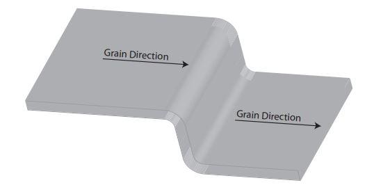
FIGURE 2. Bending across the grain (that is, when the grain direction runs perpendicular to the bend) makes for a stronger bend that’s less likely to crack.
About the Author

About the Publication

subscribe now

The Fabricator is North America's leading magazine for the metal forming and fabricating industry. The magazine delivers the news, technical articles, and case histories that enable fabricators to do their jobs more efficiently. The Fabricator has served the industry since 1970.
start your free subscription- Stay connected from anywhere

Easily access valuable industry resources now with full access to the digital edition of The Fabricator.

Easily access valuable industry resources now with full access to the digital edition of The Welder.

Easily access valuable industry resources now with full access to the digital edition of The Tube and Pipe Journal.

Easily access valuable industry resources now with full access to the digital edition of The Fabricator en Español.
- Podcasting

In this episode of The Fabricator Podcast, Caleb Chamberlain, co-founder and CEO of OSH Cut, discusses his company’s...
- Trending Articles
1
How to set a press brake backgauge manually

2
Capturing, recording equipment inspection data for FMEA

3
Tips for creating sheet metal tubes with perforations

4
Are two heads better than one in fiber laser cutting?

5
Hypertherm Associates implements Rapyuta Robotics AMRs in warehouse
