


Better bend sequencing and gauging on the press brake
The right bend sequence and gauging makes all the difference

The press brake remains one of the most challenging machines to master on the fab shop floor. Getty Images
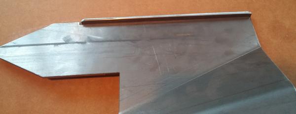
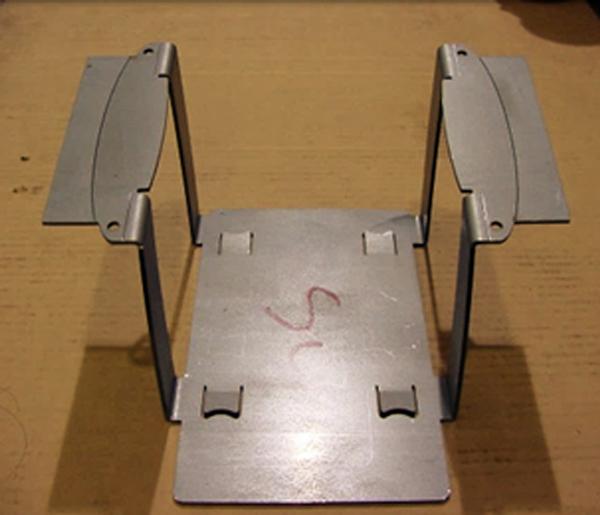
Question: I’ve been working on a challenging part (see Figures 1 and 2) made of 3/16-inch-thick steel. It has stiffeners on the left and right side that are 90-degree downward flanges, along with four internal bends. Each of the four internal bend lines run askew, unparallel to the blank edge.
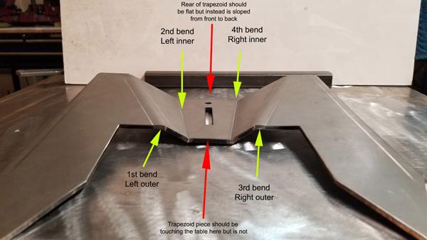
The center trapezoid shape created by the two innermost bends should sit flat on the table, and the tips of the triangle flukes should also touch the table, so there is an 8- to 10-degree slope downward from the back to the front (flukes in the front). I can form most of this part consistently, but I’m having trouble with the trapezoid shape, which isn’t sitting flat and usually has some wobble.
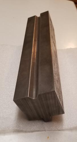
I bend everything over a special commercial die with a 0.65-in. opening (see Figure 3), performing each of the 90-degree stiffeners first. I bend the outer down-bend, then flip it over and do the inner up-bend. I then do the same on the other side (see Figure 4). The shop drawing tells me to “bend down to 150 degrees” (30-degree external angle) for the inner bend and “bend up to 152 degrees” (28-degree external angle) for the outer bend.
Unfortunately, after performing the outer bend, I find it almost impossible to start the second bend without the first bend contacting the die. So, I have to use another V die with a 0.65-in. opening to get the second bend started.
I now have about 60 of these pieces that are all wobbly and not sitting flat, and I can’t figure out how to fix them. Should I flatten them out and then rebend using a wider die? If I rebend them all from a flat piece, could doing the inner bends first make a difference and influence the trapezoid to sit flat, rather than be tilted backward?
Answer: Your thinking, for the most part, is right on track. While the die you’re using is a contributing factor, one that you can correct for easily, your problem probably has more to do with your bend sequence and the associated gauging.
Even under the best of circumstances, trying to flatten and rework a part rarely works out well and leads to badly marked-up sections on the workpiece. You never get your piece truly flat again, and you mar the workpiece. You’ll also weaken the flattened material along the bend line. It will be challenging to hit the bend in the same place, and when you do, you’ll start to see stress fractures on the outside bend radius.
The bend line will shift to the weakest point, which won’t necessarily be straight down the bend line. You’ll end up with a flattened “W” shape in the material. Some areas of the flattened bend line will thin and thus create weak areas within the part.
Even worse, you will not be able to hold any of the desired dimensions. The flattening changes the flat dimensions and causes the bend deduction to change. The overall dimension will be longer. Flattening and rebending the part will weaken the bend and the integrity of the material will be gone. This could lead to part failure once the unit has been installed in the field.
While you may get away with rehitting on a few parts, you might cause the wobbling to get worse. I know you don’t want to hear this, but remaking the parts from new blanks is the correct course of action. It will save you a lot of unnecessary aggravation, especially when the difficulty cuts deep into your profit. Trust me on this one; it is not worth the fight.
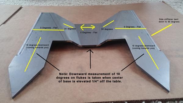
Figure 1
The part in question has internal bend lines unparallel to the blank edge. Per the shop drawing, the innermost up-bends are bent to an internal angle of 150 degrees (an external angle of 30 degrees), while the outer down-bends are formed to 152 degrees (external angle of 28 degrees).
Perfecting Your Forming Order
Because you’re starting with the 90-degree down-bends for the stiffener flanges followed by those innermost up-bends, you’re forcing yourself to bend off a downward flange, which puts you below the plane that’s parallel to the top of the die. Reordering your bend sequence will help improve your process and should take care of the trapezoid’s wobbling problem and allow you to hold the other dimensions to the print.
I would begin with the two innermost bends and work my way out from there, finishing with the 90-degree bend. Specifically, I would start with the innermost up-bend; flip the part for the outer down-bend; then perform the 90-degree down-bend for your stiffener flange. After this, spin the part around to produce the same three bends on the other side.
Gauging the Workpiece
Any variation in bend angle will change the part’s relationship to the backgauges, causing the location of the bend line to move from the position that it should be. Considering this, how do you develop a consistent gauging strategy so that all the bends lines are in the same location, side to side and bend to bend?
Your gauging strategy will depend on the type of backgauge system you have. Modern multiaxis backgauge systems have stops that are agile and designed to work with the backgauge fingers out of parallel.
Another option is to add breakaway material to gauge from, by having the additional material cut to the same angle as the bend lines in the workpiece (see Figure 5). (Note that I’m referring to the angle of your bend lines in relation to the blank edge, not the angles of the bends themselves.) This extra material keeps the bend line parallel to the gauges. Once you finish bending, you can remove the extra material.
Because of the two different angles of the four internal bend lines, you will need two breakaway pieces. To make these, try cutting the blank with two laser-stitched lines on either side. The edges should be parallel to the innermost bend line (for the 150-degree angle); the outer laser-stitch line should be parallel to the outermost bend line (for the 152-degree angle); and the inner laser-stitch line will be the edge of the formed part.
You’d form the 150-degree bend first, then break away the material along the outermost laser-stitched line, revealing an edge parallel to that 152-degree bend. After forming that bend, you’d break the innermost laser-stitch line to reveal the true blank edge, which you can use to gauge your 90-degree downward flange. Finally, you’d spin the part around and repeat the sequence on the other side.
Bending Die Modification
The die you’re using (see Figure 3) appears to be a little overbuilt. If you still have clearance problems, forcing the first bend to open and changing the part dynamic, you could easily afford to have material removed from both sides of the tool. Removing a portion for clearance should not change the function or strength of the tool.
Mastery Through Practice and Patience
Forming order and gauging are always going to be a practiced art that does take some time to learn and one that can only be acquired by spending time at the press brake, by making mistakes, and learning from them. These mistakes can be costly, especially when you need to remake an entire order.
In time, however, you should get pretty good at it—that is if you don’t let the process of learning frustrate you too much. Just keep in mind that there is a rather long learning curve to operating a press brake efficiently and with finesse. Always remember, the press brake remains one of the most challenging machines to master on the fab shop floor.
Steve Benson is a member and former chair of the Precision Sheet Metal Technology Council of the Fabricators & Manufacturers Association International®. He is the president of ASMA LLC, steve@theartofpressbrake.com. Benson also conducts FMA’s Precision Press Brake Certificate Program, which is held at locations across the country. For more information, visit www.fmanet.org/training, or call 888-394-4362. The author’s latest book, Bending Basics, is now available at the FMA bookstore.
About the Author

About the Publication

subscribe now

The Fabricator is North America's leading magazine for the metal forming and fabricating industry. The magazine delivers the news, technical articles, and case histories that enable fabricators to do their jobs more efficiently. The Fabricator has served the industry since 1970.
start your free subscription- Stay connected from anywhere

Easily access valuable industry resources now with full access to the digital edition of The Fabricator.

Easily access valuable industry resources now with full access to the digital edition of The Welder.

Easily access valuable industry resources now with full access to the digital edition of The Tube and Pipe Journal.

Easily access valuable industry resources now with full access to the digital edition of The Fabricator en Español.
- Podcasting

In this episode of The Fabricator Podcast, Caleb Chamberlain, co-founder and CEO of OSH Cut, discusses his company’s...


