


Choose the right press brake tooling for the job
Following these four rules will lead to better bending and avoid ruining tools, equipment
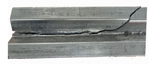
FIGURE 1 This traditional planer die with a 2-in.-wide body broke under forming tonnage.
Question: We had an incident recently where an operator was instructed to use an incorrect punch/die combination for a material. As a result, the punch cracked. I’d like to show my team examples of more extreme cases where punches and dies have exploded, or at least be able to show my operators the dangers of incorrect tool use.
Answer: I often get these requests from owners, engineers, department leads, and operators, and they all relate to improper tool selection. Many describe what happened to them when tool selection went awry, and how they ended up with tools looking like the one shown in Figure 1.The tonnage overload utterly destroyed the die, but trust me, it can get even worse. That’s because this die was a traditional planer tool and, as such, was manufactured from softer steel that was flame-hardened at best. If you overload this kind of tooling, you hear a loud noise or bang; you then might see broken pieces fall to the floor, putting the operator’s feet in harm’s way. But if the operator avoided having his foot smashed, he could return to the press brake, select another tool, and try again—maybe after he finished changing his underwear.
How could that situation get worse? Simple: The operator could have been working with an early style of precision- ground tool. Many of these tools were through-hardened to a very high Rockwell rating. Such hardening made the tools last pretty much forever, but it also made them very brittle and prone to throwing shrapnel, sometimes a very long distance—like the die in Figure 2. It’s an old precision-ground tool, and the image was taken with an old digital camera (hence the blurriness),but it helps illustrate the point. A piece from this die (which had a 0.394-in. die opening …. until it exploded) flew more than 80 ft. downrange, hit 6 ft. up on the wall, and dented the cinderblock. Oh, did I mention the broken edge was razor-sharp?
Accidents like these often happen because of poor tooling selection. For another example, check out Figure 3. No doubt, the press brake itself suffered a little permanent damage during the forming operation. The tool might have been embedded into the ram or bed. The operation might have caused ram upset, or a permanent deflection of the press brake’s ram and bed. All this shows the value of following a few commonsense rules when selecting tools.
Rule No. 1: Select the Right Die Opening
Unless you’re calculating the exact values for the die opening, you should almost always use an amount equal to eight times the material thickness—and never less than six times the material thickness. This applies to all bending operations, whether you’re producing sharp, minimum, or perfect bend radii.
If you are calculating geometrically perfect values for the die opening, and the inside bend radius is 125% of the material thickness or less, you start with the following formula: Die opening = Outside bend radius × 3.429.
From there, pick the closest die opening that you have available, then check your tonnage load to make sure you don’t overload the tools or the press brake (for more on this, see Rule No. 2).
If overloading appears likely, pick a larger opening, recalculate the load, and repeat as necessary until the operation can be completed without overloading. Note that when you are air bending, every change in the die opening will yield a different inside bend radius, which will change the bend allowance, outside setback, and bend deduction. (Ideally, this operation should be completed in engineering before the job even reaches the production floor.)
For thicker materials or larger bend radii, the formulas are a little different. These include radius, surface, and profound radius bends, all of which have inside bend radii greater than 125% of the material thickness. In these cases, the equations are:
Standard V dies = 2.5 × (Inside bend radius + Material thickness).
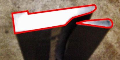
FIGURE 2 It’s a blurry, old image of an early through-hardened press brake die, but the added red outline illustrates the point. This 4-in.-long, 0.394-in. V die exploded and threw shrapnel 80 ft. downrange, denting a cinderblock wall.
Relieved, Acute, or Channel dies = 2.2 × (Inside bend radius + Material thickness)
For more on this topic, see Air forming and V-die selection.
Rule No. 2: Check the Tonnage Requirements
Always calculate the tonnage requirements for the tools you select. In general applications, the following formula is accurate. If you’re bending robust materials like high-strength steels or very soft materials, you should replace this formula with one that is more appropriate. Also note that you can find the material type multiplier by comparing a material’s tensile strength with 60-KSI mild cold-rolled steel, our baseline material. So if a material has a tensile strength of 120 KSI, the multiplier would be 2 (120/60 = 2).
Forming tonnage = {[575 × (Material thickness)2] / Die opening) /12) × Inches of bend × Material type multiplier
If the bend requires an unusual tool that performs multiple bends in a single hit, such as an offset punch and die set (which makes two bends at a time), you need to apply the appropriate multiplier to the formula. Figure 4 shows several examples of those values.
For instance, say you have a tool that makes a four-bend hat channel in one hit. We’re using our baseline material, 60,000-PSI-tensile mild cold rolled-steel. In this application, the steel is 0.060 in. thick. Referring to the chart, you multiply the 600 value by the material thickness to arrive at the tonnage value:
600 × 0.060 = 36 U.S. tons
And just like when you use standard press brake tonnage charts, you need to factor for the material type, comparing the tensile strength of the material at hand with the 60-KSI baseline. For stainless steel the multiplier might be 1.4, and for soft aluminum it might be 0.50.
Rule No 3: Select the Right Punch
Try to use a punch nose radius as close as possible to—but does not exceed—the naturally floated air-forming radius value. If the punch nose radius exceeds the floated radius value, the part will take on the punch nose’s larger radius and the required tonnage to make the bend will increase. That change in radius will change the bend deduction and the part’s final dimensions.
Rule 4: Avoid Bending Sharp
If possible, avoid a sharp-bend relationship between the punch nose and material. Bending sharp during an air form causes the punch nose to pierce the naturally floated inside bend radius, pushing it into a parabolic shape. This changes the bend allowance, outside setback, and bend deduction. For more on this topic, search for “How an air bend turns sharp” on thefabricator.com. You also can review “How to avoid a sharp bend” and “A grand unifying theory of bending on the press brake,” a four-part series from 2015.
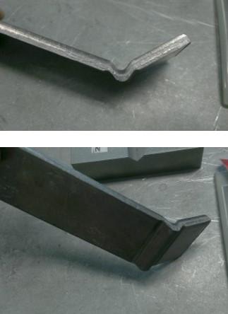
FIGURE 3 This 0.25-in.-thick material was formed in a 0.630-in. die opening—just a tad small, you think? I’m being sarcastic, of course. The operator was lucky. Fortunately, this die did not break. But the part itself is a little worse for wear, and the tonnage load must have been phenomenal.
Take Pride in the Product
Avoiding crashed tools, smashed parts, or ruined press brakes as you try to form parts into dies too small for the job—to be honest, it doesn’t require a lot of effort. It's only a matter of following a few basic rules.
Note that all this must start in engineering and work its way down to the shop floor. It’s not just about the operator anymore; they’re only a link in the chain. Today almost everyone is air forming, which means having operators arbitrarily select tools is no longer a viable option as it was in the days of coining and bottom bending.
A few shops are still bottom bending, of course, but even then, press brake operators sometimes need to make additional tooling choices to correct errors in the blank size or build legacy parts. But in those cases, the tooling selection should be committed to a setup sheet so that the tool choice becomes standard for a specific job. Operators should not be reselecting tools from scratch every time the job comes around.
In shops that air-form parts, engineers should go to the shop floor and, without judgment, ask operators what bending methods they use with which material types. Next, they should get a list of the tooling that the operators have available to work with at their machine.
Then the engineering department can design parts based on tooling available and the forming processes used. When engineers have the necessary information and know what’s practiced on the shop floor, it gives operators no reason to try to prove engineers wrong. And if engineers design around available toolsets, press brake operators can start making good parts right out of the gate.
I realize I’ve mentioned this before many times in my columns, but it’s worth repeating: If you implement these changes and design parts around available tooling, your operation will produce quality parts faster. These best practices will allow everyone in the chain of production to take pride in the final product.
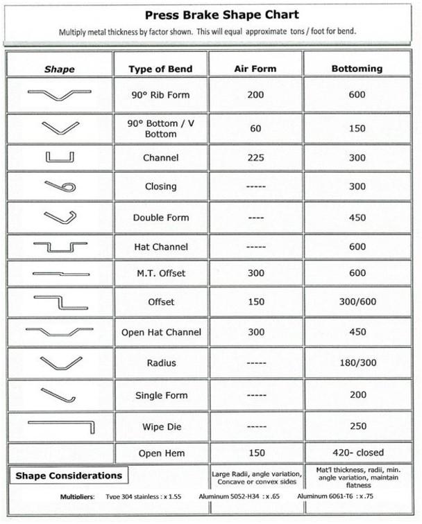
FIGURE 4 Use the following multiplier values for geometries that are not a single air formed bend. Chart courtesy of FreeTechnicalCharts.com.
About the Author

About the Publication

subscribe now

The Fabricator is North America's leading magazine for the metal forming and fabricating industry. The magazine delivers the news, technical articles, and case histories that enable fabricators to do their jobs more efficiently. The Fabricator has served the industry since 1970.
start your free subscription- Stay connected from anywhere

Easily access valuable industry resources now with full access to the digital edition of The Fabricator.

Easily access valuable industry resources now with full access to the digital edition of The Welder.

Easily access valuable industry resources now with full access to the digital edition of The Tube and Pipe Journal.

Easily access valuable industry resources now with full access to the digital edition of The Fabricator en Español.
- Podcasting

In this episode of The Fabricator Podcast, Caleb Chamberlain, co-founder and CEO of OSH Cut, discusses his company’s...
- Trending Articles
1
How to set a press brake backgauge manually

2
Capturing, recording equipment inspection data for FMEA

3
Tips for creating sheet metal tubes with perforations

4
Are two heads better than one in fiber laser cutting?

5
Hypertherm Associates implements Rapyuta Robotics AMRs in warehouse
