


Metal Forming Specialist
The fabrication market is pushing for lower costs and less weight, and aluminum extrusions, which often need to be curved, are serving that need. A well-designed extrusion that’s curved effectively can create a seamless link in a structure and ultimately lead to fewer problems for the bending subcontractor, the fabricator, and the final customer.
Technically speaking, all sizes of extrusions can be bent, yet small bending shops often max out at profiles 10 in. high or 6 in. wide. When a fabricator looks for a bending subcontractor, it should review the company’s experience with bending similar extrusions. One bending specialist might say certain job attributes are acceptable, and another might say that they aren’t.
It goes back to a company’s specific extrusion bending experience and, not least, the technology the bending shop has. For instance, if a shop says it can form large structural profiles, it needs a bending machine with wide shaft centers.
Whether thinking about subcontracting or performing the work in-house, a fabricator should start with two basic questions: What design attributes make an extrusion easy to bend? and If all design accommodations can’t be made, what are the options? Answering these two questions upfront—before an aluminum extrusion bending project starts—can help a fabricator avoid a tremendous number of headaches down the road.
When it comes to forming aluminum extrusions, a design engineer has a lot to consider. This goes beyond the typical cost factors, including weight and the alloy used in the extrusion, which are natural considerations for any large-scale project.
A design engineer should have a basic idea of what makes an extrusion bendable. The thickness of various areas of an extrusion will affect the section’s bendability. The same goes for symmetry. Quite often the need to save money renders an extrusion unbendable.
The alloy the designer chooses will determine not only the extrusion’s strength, corrosion resistance, weight, and durability, but also its bendability. As in any forming situation, some extruded aluminum grades are more bendable than others.
Most aluminum extrusion bending involves 6000-series alloys, as these aluminums offer good strength and formability. The ideal temper depends on the application. T6 offers the greatest strength but is the most difficult to form (see Figure 1). For tighter radii, less than 10D (a radius less than 10 times the diameter), a designer should consider a maximum temper of T4. T0 offers the best formability but has little strength and is susceptible to damage during fitting and operation. A bending specialist can send out a formed section for heat treating, artificially aging the profile to a higher temper, but this of course adds cost.
Surface treatments and finishing requirements also need to enter the equation. For instance, consider an extrusion that’s anodized, a common treatment to protect aluminum in harsh environments. Bending the section to a tight radius will “craze” the surface as microcracking spreads across the anodized layer, which lacks ductility. Crazing occurs in the built-up area of anodized coating and not the substrate. To avoid this, an operation should perform anodizing after bending.
Painting or powder coating, however, need not always occur after bending (Figure 2). A well-prepared painted or powder-coated section can be formed free of marking if the radius is not so tight that it’s near the profile’s limit, and the section is relatively symmetrical.
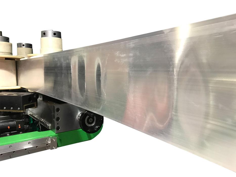
Figure 1
The formability of 6000-series aluminum extruded profiles varies with the temper. The 9- by 2.5-in. workpiece with a 1/16-in.-thick wall on the left is a T6 material, and even the slightest bend profile formed a ripple. On the right, the same workpiece, though at a bendable temper, formed cleanly to a 34-in. radius. This profile was formed successfully on a machine with 44-in. centers.
The complexity of the extruded shape also plays a role. Making a more complex shape can reduce some costs, like those associated with assembly, but at the same time may increase other costs—including the bending costs. Moreover, if the bending machine and its tools can’t reliably control an extrusion’s movement during bending, the process becomes less stable, costlier, and sometimes impractical or outright impossible.
The designer also must think of how the extrusion will be used. If certain faces of extruded sections are visible and cosmetically critical, the designer should ensure these faces can be formed free of marking.
Quite often a small design change to a section can make it bendable, or at least bendable to the radius needed. When creating the profile, designers should try to keep as much symmetry as possible in line with the bend axis.
When a section is asymmetric, a twisting (torsional) force reacts to the bending force. The less symmetry a section has, the more severe the twisting force during bending becomes. This creates problems during bending as this is often a less predictable force. Controlling it usually means applying pressure to another axis, which can create additional issues.
Figure 3 shows initial extruded sections from a designer on the left and, on the right, those same designs modified for bending to a tighter radius. Notice how symmetry and internal support play key roles, as does having a shape (like a sufficiently deep flange) that bend tooling can grasp consistently. Of course, it’s not always possible to make these kinds of changes to an extruded shape. In these cases, it’s always a good idea to seek out a specialist with more experience.
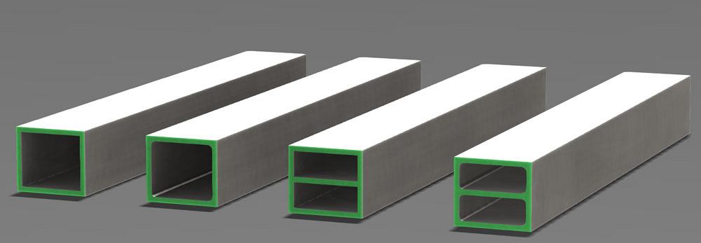
Square hollow sections can cause problems in bending for two main reasons. First, designers often create these sections with square internal corners, which can cause cracking and even fracturing in hard material. Adding very little cost, a designer simply can round the corners and eliminate this stress point.
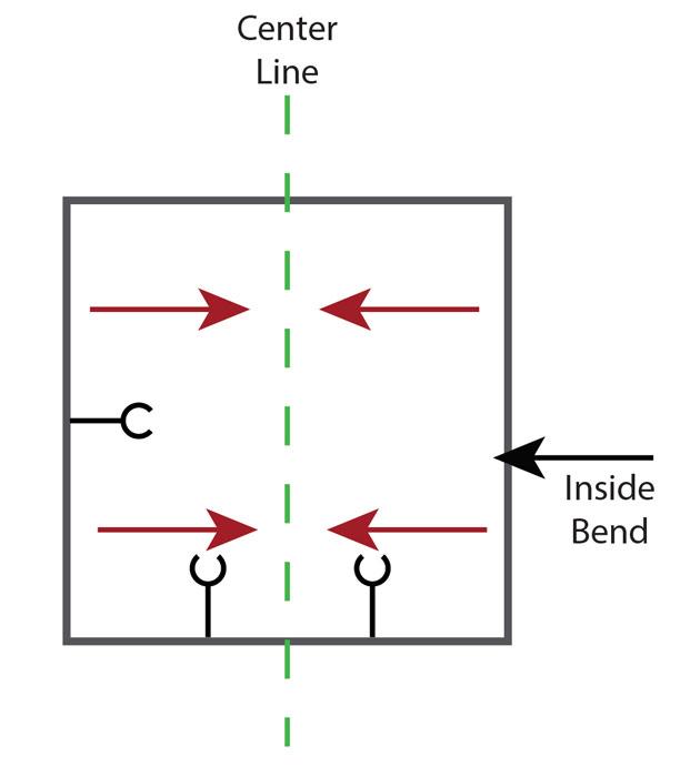
Second, the hollow section is likely to become concave on the inside face if the wall thickness is not adequate. This indicates the shape can’t handle the required bending forces. That’s because forces during bending act toward the center and toward the neutral axis, which is in the middle of a symmetrical section.
To counteract this, designers have several options. They can increase the wall thickness, but that’s often not possible because the cost is too high. Alternatively, they can add a stiffener or a rib in the plane of bending, add a radius to the internal corners, or do both (see Figure 4). Adding stiffeners and internal radii naturally increases the weight of the profile, but this may be acceptable for the improved quality.
Asymmetry is the enemy of easy bending, which is why channel sections can be so difficult to form (see Figure 5). Their severely asymmetric shape undergoes a large twisting force during bending, and the legs try to move toward the central axis. Altering the design—to one with a base that’s equal to or a little wider than the legs—will help bending specialists control the twisting a little better.
Channel sections often serve a purpose, like being part of a track or transport system. Most bending specialists should be able to form them correctly, as long as tolerances are specified in a few key areas. If a fabricator is subcontracting the work, it should send parts or fittings to the bending specialist to ensure everything fits as it should.
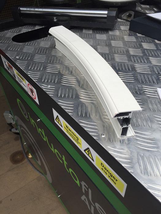
Figure 2
This prepainted aluminum profile was bent free of marking
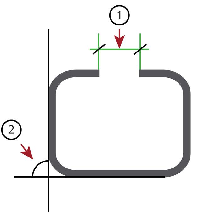
Any order for an aluminum forming specialist should state the requirements that would allow the section to fit into or freely move within the assembly as designed. The order also should specify the gap tolerance (No. 1 in Figure 6) for the trolley or slide, as well as a twist tolerance (No. 2 in Figure 6) that will ensure the trolley will not hit the profile.
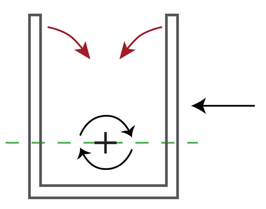
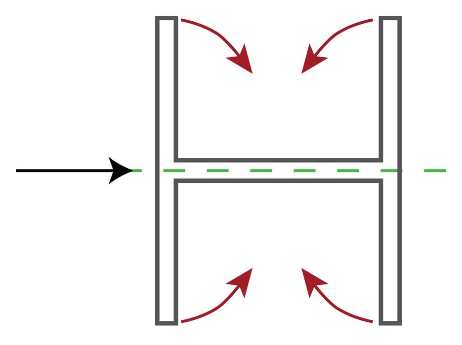
Consider the aluminum structural shape in Figure 7, being bent in the direction shown by the black arrow. All legs are forced toward the center (as shown by the red arrows in the figure)—a tendency particularly noticeable on structural joist-type sections.
If this were a conventional carbon steel beam, the flanges would be pulled in the opposite direction, placing tension on the web and, therefore, keeping the web flat. This technique generally isn’t suitable for aluminum, though, so other techniques come into play.
Ideally, the designer changes the profile shape or adds features to allow for easy forming. But in the real world, of course, this isn’t always possible, often because the desired features in a section just won’t allow for any significant change.
A bending company could have a large-radius mandrel bending machine, which can support the section internally during bending. But this is a specialty process, and not many companies own such machines.
Another solution is to fill the profile; suitable materials include low-melting-point alloys; a wax-type, water-soluble filler; flexible nylon; and hard-packed sand to help support the shape. Each filler material has its advantages and disadvantages. Some of these options usually are provided only by larger bending specialists in a particular market.
Aluminum extrusions can have special features that can greatly simplify subsequent fabrication and assembly. But when adding such features, designers need to place them carefully and consider how those features will affect bending.
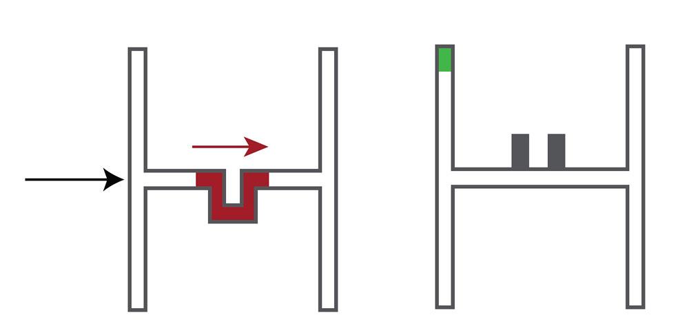
Screw ports, a great time-savings idea for fixing the end caps onto profiles, are a prime example (see Figure 8). If the designer places these perpendicular to the bend radius, these ports will most likely move to the centerline, unless they’re supported internally. When placed in line with the radius, the ports aid bending as they have the effect of a stiffening rib. Supplying the end cap itself to the bending specialist, which can use it as a check tool, is essential.
Nut tracks are another good example. These features help secure extruded sections together. They’re essentially a channel designed to fit a nut or bolt head tightly between the flats, thus preventing the nut or bolt head from spinning.
Designers should ensure that the nut track is not in the bending line, as shown on the left in Figure 9. During bending about an axis, the forces must be able to transfer easily across the profile. If possible, it is always better to add a screw port onto one side of the profile, as shown on the right in Figure 9.
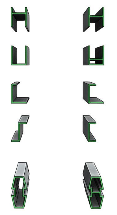
Figure 3
Aluminum extrusions on the left are original designs, while those on the right are designs modified for bending to tighter radii.
If the section is somewhat symmetrical, it probably can be bent to the very end of the profile, eliminating the need to cut the straight remnant after bending. Whether this can be done efficiently and repeatably goes back to the extrusion’s design.
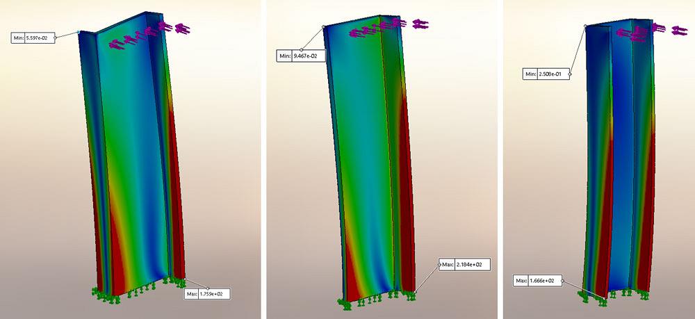
Consider the finite element analyses (FEAs) of the three different profile shapes in Figure 10. The extrusion on the left is a Z-type section, and the red (stressed) areas show distinctly uneven areas under bending forces. The middle profile is an angle, which also is asymmetric but shows less stress on one side and, therefore, less twisting force. The profile on the far right is symmetric to the bending axis and, therefore, bends evenly to the very end of the section.
An extrusion may not form so well without good planning, and those FEAs illustrate a critical point: It really is all about managing stress. This applies when designing not only the overall profile shape, but any special features and coatings. Ultimately, the less stress an extruded aluminum section endures during bending, the better the results will be.
Craig Barnshaw is managing director at U.K.-based Inductaflex Ltd., 44-333-939-8888, www.inductaflex.com, represented in the U.S. by Trilogy Machinery, Belcamp, Md., 410-272-3600, www.trilogymachinery.com.

The Fabricator is North America's leading magazine for the metal forming and fabricating industry. The magazine delivers the news, technical articles, and case histories that enable fabricators to do their jobs more efficiently. The Fabricator has served the industry since 1970.
start your free subscription
Easily access valuable industry resources now with full access to the digital edition of The Fabricator.

Easily access valuable industry resources now with full access to the digital edition of The Welder.

Easily access valuable industry resources now with full access to the digital edition of The Tube and Pipe Journal.

Easily access valuable industry resources now with full access to the digital edition of The Fabricator en Español.
In this episode of The Fabricator Podcast, Caleb Chamberlain, co-founder and CEO of OSH Cut, discusses his company’s...


