


Marketing Communications Coordinator
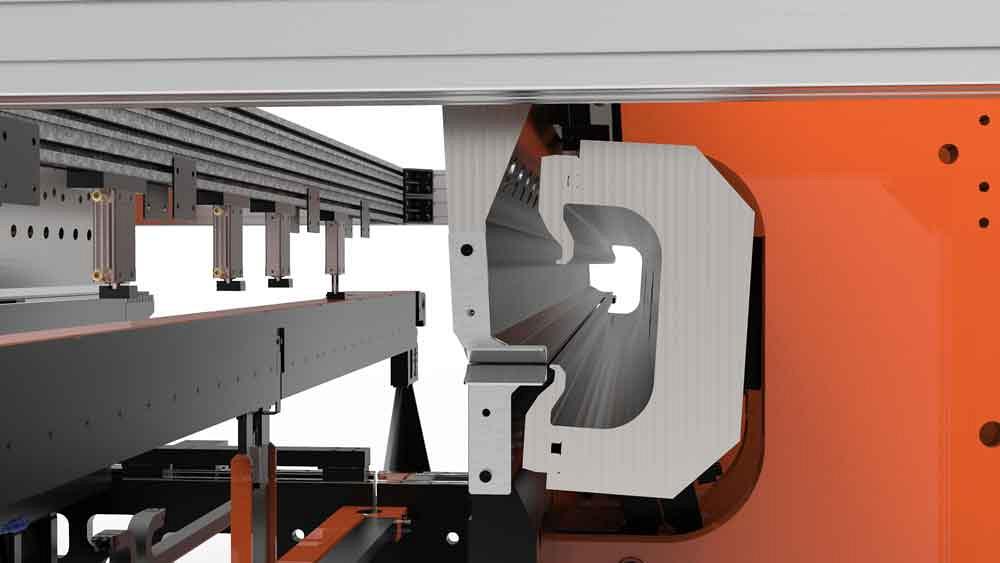
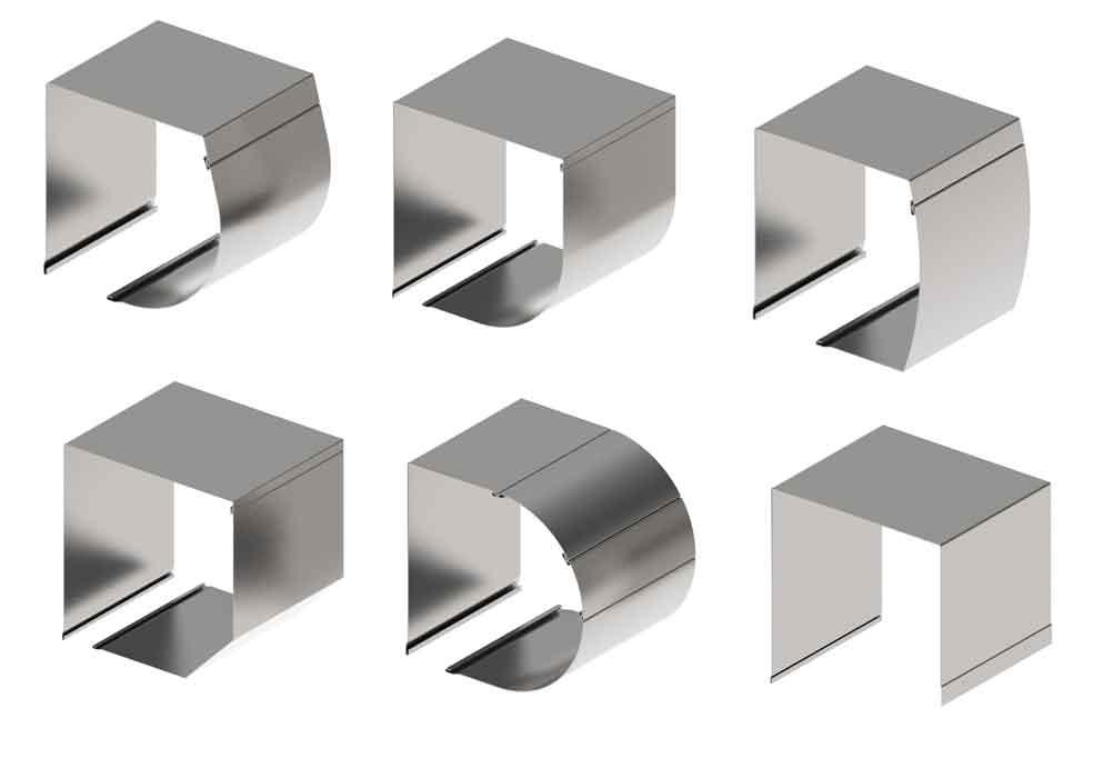
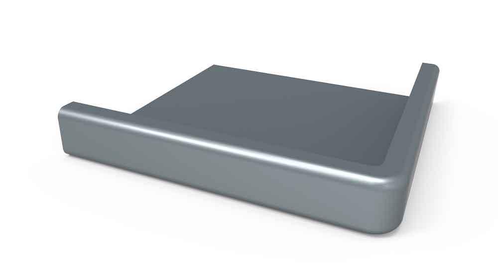
Figure 1
In CNC bending, commonly known as panel bending, the metal is clamped in place, and upper and lower bending blades form positive and negative flanges.
A typical sheet metal job shop might have a combination of bending systems. Press brakes are most common, of course, but some shops also invest in other forming systems like panel bending and folding. All these systems help operations form various parts without the need for dedicated tooling.
Sheet metal forming in high-volume production has evolved too. Such factories no longer need to rely on product-specific tools. They now employ modular lines that can meet a variety of forming demands, combining panel bending with numerous variants of automated forming, from corner forming to press braking and roll bending. And nearly all of these modules perform their operations with little if any product-specific tooling.
Automated bending lines for sheet metal today use “bending” in the generic sense. That’s because they offer various types of bending beyond what’s popularly known as panel bending, also known as CNC bending.
CNC bending (see Figures 1 and 2) remains one of the most common processes on automated lines, mainly because it’s so flexible. A sheet is moved into position with either a manipulator (with the characteristic “foot” securing and sliding the sheet) or with a special conveyor. Conveyors tend to work well if sheets have previously cut holes that would make it difficult for a manipulator to move them.
Two fingers emerge from below to center the part prior to bending. After this, the sheet is positioned below clamping tools that descend and clamp the workpiece in place. Bending blades from below move up to form positive bends, while blades from above descend to form negative bends.
Think of the bending mechanism as a large “C,” with the upper and lower blades at either end. The maximum flange length is governed by the throat, or the back of the “C,” behind the bending blades.
The process boosts bending speed. Typical flanges, be they positive or negative, can be formed in half a second. The bending blade movement is infinitely variable, allowing for many forms, from the simple to the incredibly complex. This also allows the CNC program to alter the outside bend radius by changing the exact position of the bending blades. The closer the blade is to the clamping tool, the tighter the part’s outside radius, down to about twice the material thickness.
Such variable control also provides flexibility when it comes to bend sequence. In some applications, should the final bend on a side be negative (folding downward), the bending blades can move out of the way, and a conveyor mechanism lifts the piece and carries it downstream.
Conventional panel bending does have drawbacks, especially when it comes to cosmetically critical work. The bending blades tend to move in a fashion whereby the tip of the blade doesn’t stay in one place during the bending cycle. It instead tends to drag slightly, roughly analogous to how a sheet drags along the die shoulder radii during a bending cycle on a press brake (though in panel bending, the dragging occurs at just one point of contact, between the bending blade and the part’s outside surface).
Enter swivel bending, analogous to folding on stand-alone machines (see Figure 3). In this process, a bending beam swivels in such a way that keeps the tool in constant contact with a single location on the workpiece’s outside surface. If the application requires, most modern automated swivel bending systems can be designed so that the swivel bending beam can bend both up and down. That is, they can rotate upward to form a positive flange, reposition itself to rotate around a new axis, and then bend a negative flange (or vice versa).
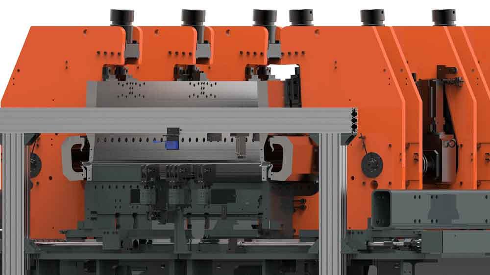
Figure 2
Instead of a traditional manipulator, this panel bending unit uses a special conveyor to manipulate the workpiece.
Some swivel bending operations—called dual swivel bending—use two beams to create special forms, like Z shapes involving alternating positive and negative bends. Single-beam systems can swivel-bend these forms, but to access all the bend lines, the sheet needs to be flipped over. A dual-beam swivel bending system can access all bend lines in a Z bend without flipping the sheet.
Swivel bending does have its limitations. If the automated application calls for very complex geometries, CNC bending—with its infinitely variable movement of the bending blades—is the better choice.
Swivel bending challenges also arise when the last bend is negative. While bending blades in CNC bending can move back and out of the way, swivel bending beams cannot move in this fashion. A final negative bend would require someone to physically slide the piece out. While doable in a system that requires manual intervention, this usually isn’t practical in a fully automated bending line.
Automated lines aren’t limited to panel bending and folding—so-called “horizontal bending” options in which the sheet stays flat while the flange bends up or down. Other forming processes expand the possibilities. They include a specialized operation that incorporates press braking and roll bending. The process was invented for making products like roller shutter boxes (see Figures 4 and 5).
Picture a blank conveyed into a press braking station. Fingers slide the blank laterally over a brush table and between an upper punch and lower die. Like in other automated bending processes, the blank is centered, and the controller knows where the bend lines are, so there’s no need for a backgauge behind the tooling.
To perform bending with a press brake operation, the punch descends into the die, makes the bend, and the fingers advance the sheet to the next bend line, just as an operator would in front of a press brake. The operation also can bump-bend (also called incremental bending) a radius, just like a conventional press brake can.
Of course, like on a press brake, bump bending on an automated line can leave bend-line marks. And for bending a large radius, using bumping alone would most likely increase cycle time.
Here’s where the roll bending function comes into play. When the upper punch and lower die are in a specific position, the tools effectively turn into a three-roll roll bender. The tip of the upper punch is the upper “roll,” and the shoulders of the lower V die are two lower rolls. The machine’s fingers push the sheet through to create the radius. After bending and rolling, the upper punch moves up and out of the way, leaving room for the fingers to push the formed part forward and out of the work envelope.
Roll bending on an automated system can quickly create large, sweeping curves. But for certain applications, there’s an even faster way. It’s called variable-radius bending, a patented process initially developed for aluminum components in the lighting industry (see Figure 6).
To get a rough idea of the process, think of what happens to a ribbon when you drag it between a scissors blade and your thumb. It curls. The same basic idea applies to variable-radius bending, only the tool applies a light, careful touch, and the radius forms in a very controlled manner.
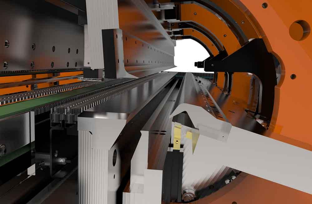
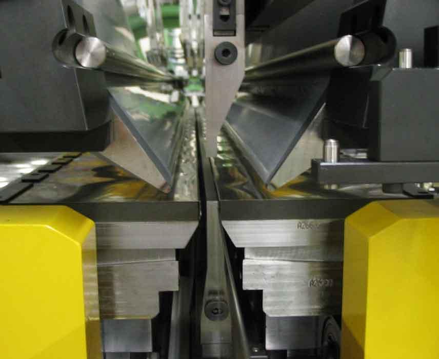
Figure 3
In swivel bending, or folding, a bending beam swivels in such a way that keeps the tool in constant contact with a single location of the sheet’s outside surface.
Picture a thin workpiece clamped in place, with material to be formed completely supported underneath. A bending tool descends, presses against the material, then moves forward toward the clamp holding the workpiece. The tool’s motion induces tension and causes the metal to “curl” behind it to form a specific radius. The tool’s force against the metal dictates the amount of induced tension and the resulting radius. Moving in this fashion, a variable-radius bending system can create a large-radius bend extremely quickly. And because one tool can create any radius (again, it’s the pressure the tool applies, not the shape, that dictates the form), the process requires no product-specific bending tools.
Corner forming in sheet metal presents unique challenges. An automated process was invented for the facades (cladding panels) market. The process eliminates the need for welding and produces nicely curved edges, important for cosmetically critical products like facades (see Figure 7).
You start with a blank shape that’s cut to allow for the desired amount of material on each corner. A specialized bending module forms a combination of sharp and soft radii into the adjacent flanges, creating a “prebend” flare for subsequent corner forming. Finally, a corner forming tool—either integrated into the same station or in another station—creates the corner.
Once an automated line is in place, it’s not an immovable monument. It’s like building with LEGO®s. Stations can be added, rearranged, and redesigned. Say one part in an assembly previously required a secondary welding operation in the corner. To aid manufacturability and reduce costs, engineers eliminated welding and redesigned the part with a clinched joint. In this case, an automated clinching station could be added to the bending line. And because the line is modular, it wouldn’t require a complete teardown. It would be like adding another LEGO block to the larger whole.
All this makes automation inherently less risky. Imagine a line designed to produce a dozen different parts in sequence. If that line used product-specific tooling, and the product line changed, tooling costs could be tremendous, considering the line’s complexity.
But with flexible tooling, a new product might only require the company to rearrange the LEGOs. Add a few bricks here, rearrange a few other bricks there, and you’re back up and running. It’s not quite this simple, of course, but reconfiguring a line isn’t a monumental task either.
LEGO is an apt metaphor for automated bending lines in general, whether they are processing batches or kits. They achieve levels of forming productivity common for lines with product-specific tooling—only without any product-specific tooling.
Entire factories have been designed around batch production, and changing them over to kit-based production isn’t easy. Rearranging the entire factory can require a prolonged shutdown period—a costly proposition for factories that produce hundreds of thousands or even millions of pieces a year.
That said, for some high-production sheet metal bending operations, especially greenfield plants that work with a fresh slate, kit-based, high-volume forming has arrived. For the right application, the returns can be massive. In fact, one European manufacturer shortened its lead time from 12 weeks to just one day.
This doesn’t mean the batch-to-kit conversion never makes sense in existing factories. After all, shortening lead times from weeks to mere hours would provide a huge return on investment. But the initial costs can be too large for many operations to take the leap. That said, for a greenfield location or an entirely new line, kit-based production can make economic sense.
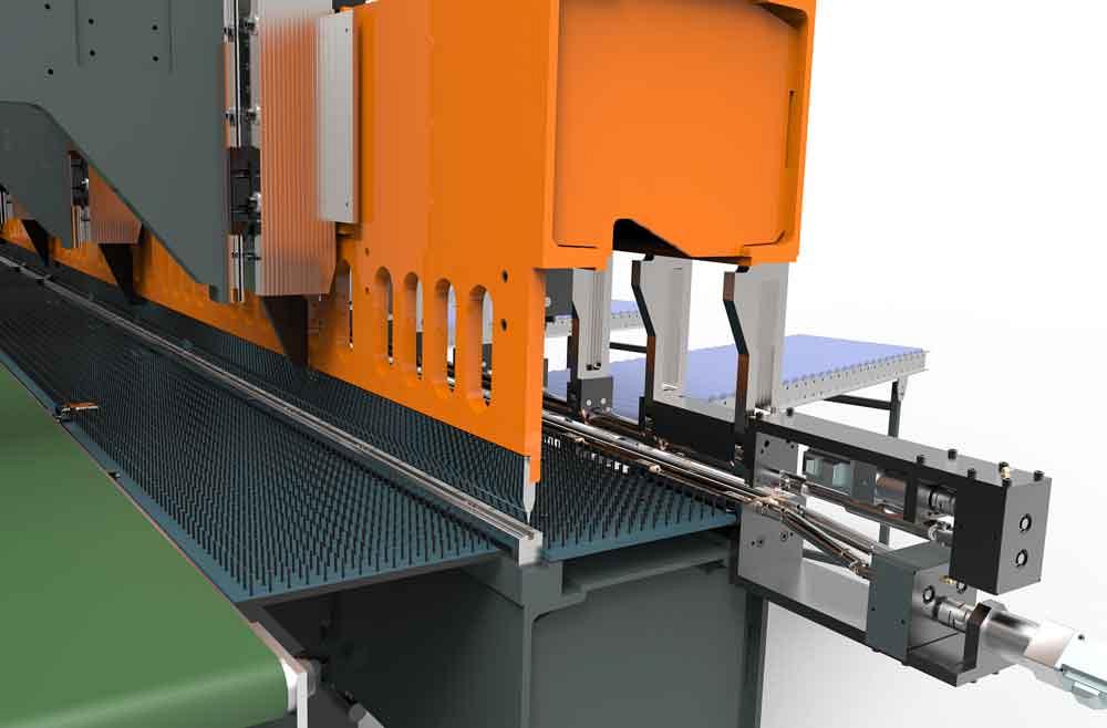
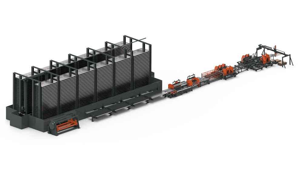
Figure 4
In this combination press brake and roll bending module, a sheet can be placed and bent between the punch and die. In roll bending mode, the punch and die are positioned so the material can be pushed through to form a radius.
When designing a high-volume line around kit-based production, consider the feeding method carefully. A bending line might be designed to accept material directly from coil stock. The material would be uncoiled, leveled, cut to length, sent through a punching module, then sent through various forming modules designed specifically for a single product or product family.
All this sounds extremely efficient—and it is, for batch processing. But converting a coil-fed batch-processing bending line to kit-based production usually isn’t practical. Forming a kit of disparate parts sequentially would most likely require different material grades and thicknesses, which would require a coil change. That can create up to 10 minutes of downtime—not long for high-mix/low-volume fabrication, but an eon for a high-speed bending line.
Similar thinking goes for a conventional destacker in which a suction mechanism picks and feeds individual blanks into the punching and forming line. These often have space for only a single blank size or perhaps a handful of different blank geometries.
For most kit-based bending lines, shelving systems suit best. Shelving towers can store dozens of different blank sizes that can be delivered into the line on demand, one unique part after another.
Automated kit-based production also needs reliable processes, especially in forming. As anyone who has worked in sheet metal bending knows, sheet metal characteristics vary. Thicknesses can vary from batch to batch, as can the tensile strength and hardness, and all this changes the forming characteristics.
This isn’t a major problem in batch processing in an automated bending line. Products and their associated lines usually are designed to handle material variation, so an entire batch shouldn’t be out of spec. But again, sometimes materials vary to such an extent that the line can’t compensate. In these cases, if you cut and form 100 pieces and find a few are outside specification, you simply rerun five more and, in a matter of minutes, you have 100 pieces for the next operation.
In a kit-based automated bending line, every piece has to be just right. For maximum productivity, these kit-based lines run in a highly choreographed fashion. If a line is designed to run, say, seven different parts sequentially, the automation runs in that sequence, from the beginning to the end of the line. If Part No. 7 is not good, you can’t just rerun Part No. 7, because the automation isn’t programmed to handle that single part. Instead, you’d need to halt the line and begin again with Part No. 1.
To prevent this, automated bending lines use real-time laser-based angle measurement, which quickly checks every bend angle, allowing the machine to correct for variances.
Such quality checks are vital to ensure a production line maintains kit-based flow. With the process perfected, a kit-based production line can deliver tremendous time savings, shortening lead times from months and weeks to just hours or days.
Werner van de Burgt is marketing communications coordinator for WEMO

The Fabricator is North America's leading magazine for the metal forming and fabricating industry. The magazine delivers the news, technical articles, and case histories that enable fabricators to do their jobs more efficiently. The Fabricator has served the industry since 1970.
start your free subscription
Easily access valuable industry resources now with full access to the digital edition of The Fabricator.

Easily access valuable industry resources now with full access to the digital edition of The Welder.

Easily access valuable industry resources now with full access to the digital edition of The Tube and Pipe Journal.

Easily access valuable industry resources now with full access to the digital edition of The Fabricator en Español.
In this episode of The Fabricator Podcast, Caleb Chamberlain, co-founder and CEO of OSH Cut, discusses his company’s...


