


How to deal with angular variation on the press brake
Press brake operators should be sure to check material consistency and forming method
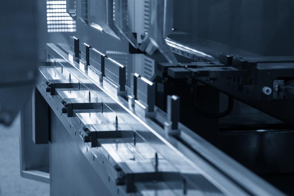
Modern press brakes and precision-ground tools are made with precision air forming in mind. If machine operators run into trouble, they should verify forming method and check the material. Getty Images
Q: We recently purchased a belt-driven servo press brake, which now sits alongside an older hydraulic press brake. On the older brake, we are bottom-bending using a 0.315-in., 90-degree V die with a 0.032-in. radius, along with an 86-degree gooseneck punch. On the new brake, we are air bending using newly purchased precision-ground tooling with the same 0.315-in. V die, because it worked well on the old machine and we wanted to try to achieve the same radius and bend deductions. The die angle is 86 degrees and the punch angle is 80 degrees.
The beauty of this new machine is that it should be able to calculate reasonably accurate depths and backgauge settings. Once you know your correction factor for a given length, it should compensate when you enter a new length. This should make it easier for the operator, but it seems our setup is not standard. The output is not as expected.
The new machine is struggling to target the right depth settings. This might be because the die opening is closer to 5x material thickness (not the recommended 6x to 8x material thickness). We use offline 3D software, but we still need to correct the backgauge settings.
On the new machine, we input the desired angle, and the machine calculates the depth the tooling should go. If the angle is off by a few degrees, we enter a correction value. However, we aren’t experiencing just 1 or 2 degrees of difference. The machine bends to 10 degrees less than what we need. Further, we need to enter correction factors closer to 12 degrees to get the 10-degree correction.
In theory, the new machine’s design does not require crowning. But when it’s loaded with the full length of tooling, if we bend a 36-in. length, the bent angle will be 92 degrees over the last 3 in. on either end but 90 degrees everywhere else. If we bend a 72-in. part with the same tooling, we get a similar inconsistency, with the bend angle going from 90 to 92 degrees on the last 3 in. at each end. But along the rest of the bend length, we achieve 90 degrees, even in the area where the 36-in. part went to 92 degrees.
The same holds true for a 120-in. part. The area where the 72-in. part was overbent will come out at 90 degrees, but the last 3 in. on either end of the 120-in. part will go from 90 to 92 degrees.
Do you have any experience with servo belt-driven machines? Would this be expected with our setup?
A: Let’s start with the machines. They are not the heart of your issue, nor are the controllers. The repeatability and accuracy of modern press brakes are genuinely exceptional, producing just microns of variation bend to bend.
Tooling isn’t your primary problem either. You’re using precision-ground tools, which, like the press brake, are exceptionally accurate. However, your tools do play a role in your conundrum, which I’ll get to in a moment. Overall, you face two issues: the material and the method of forming.
Bottoming Versus Air Forming
Because you’re using two different forming methods, bottoming and air forming, you are going to see a difference in the part dimensions produced by the two machines. Bottoming forces the punch nose radius into the part (see Figure 1). Air forming develops a “floated” bend radius as a percentage of the die opening, based on the 20% rule (see Figure 2). The 20% rule is just a name, based on the percentage used for stainless steel. Our baseline 60-KSI-tensile-strength mild steel forms an inside radius that’s about 16% of the die opening.
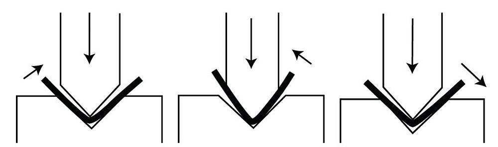
FIGURE 1. In bottoming, there is clearance between the punch and die. The punch descends and the material wraps around the punch nose. As the punch continues to apply pressure, the material is forced down to conform with the die angle.
These two methods will not produce the same inside bend radius or bend deductions. The difference won’t be enough to make the parts go out of tolerance specified on the print; they will just be slightly different.
Die Opening, Forming Pressure, and Angular Variation
As you noted, you are using a relatively small die opening, 5x instead of 8x material thickness. The smaller you make the die opening while maintaining the same material thickness, the greater the amount of angular variation you will see from bend to bend (see Figure 3).
We call angular variations down the bend length the canoe effect. The angle in the center of the bend length may be on target, but you get a different bend angle at the ends.
The traditional way to correct this is through an antideflection device or using paper shims to create a crown at the center of the tooling. But here, too, the narrower the die relative to the material thickness, the harder it will be to adjust for and control.
As you mentioned, some belt-driven servo systems take a different approach to achieving consistent forming force across the bed. Regardless, forming tonnage consistency probably isn’t the main culprit behind your problems.
How Consistent Is Your Material?
On your older hydraulic press brake, you’re bottoming, which means you’re basically stamping the punch nose radius into the material. When bottoming, minor variations in the material such as thickness, material grain direction, and yield strength do not affect the bend angle very much. In effect, bottoming takes away through force most if not all of the issues that material variation can cause. Still, that same force can damage the press brake and tooling if done incorrectly. Bottoming is a valid option for forming, but it does require a different skill set from air forming.
Air forming also can produce exceptional parts, but if your material is inconsistent, the forming method can have issues that manifest as angular variations. All this is made worse as the die opening gets narrower relative to the same material thickness.
Note that inconsistent material can still be within the mill’s thickness and strength tolerance zone. For instance, A36 has an average tensile strength of 60,000 PSI. But it also has a tensile strength tolerance zone from 55,000 to 79,800 PSI, along with a minimum yield strength of 36,000 PSI. Now add that to the thickness tolerance zone from 0.053 to 0.067 in. for 16-ga. sheet metal. That is a lot of variation, but it’s still within the material tolerances. On top of all that, you also have to consider the natural grain direction of the material. Forming with and against the grain requires different amounts of forming pressure.
Your controller can only assume the averages of these values when calculating the bend angle and depth of penetration into the die space. It is common to make some angle adjustments at the machine to compensate for the material variations. The length of bend also plays a role, so an angle adjustment of 10 to 12 degrees is not out of line.
Bending Method and Designing the Flat
Can you design a part in the flat to be formed with bottom bending, then take that same flat and air form it to achieve the same results? No, but they will be close.
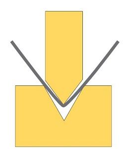
FIGURE 2. Air forming develops a floated inside bend radius that forms as a percentage of the die opening.
Again, changing the bending methods changes the way the radius is formed. So, your inside bend radius will be different even if you use identical die widths on both machines. The flat can be corrected to the dimensional halfway point so you can produce a consistent part on either machine from the same blank.
Aim for Consistency
To minimize angular variation, avoid narrow die widths and try making your forming method consistent between your two machines. Bottoming on your old hydraulic brake can give you great angular consistency because, again, the die angle sets the bend angle. But air forming also offers high angular stability and lower tonnage requirements. It’s the industry’s dominant bending method for a reason. Moreover, the high precision offered by modern machines, including servo-driven systems, was designed with air forming in mind.
Trust me, these issues are not caused by the machine, the controller, or the tools you are using. Instead, they are related to the forming method and material.
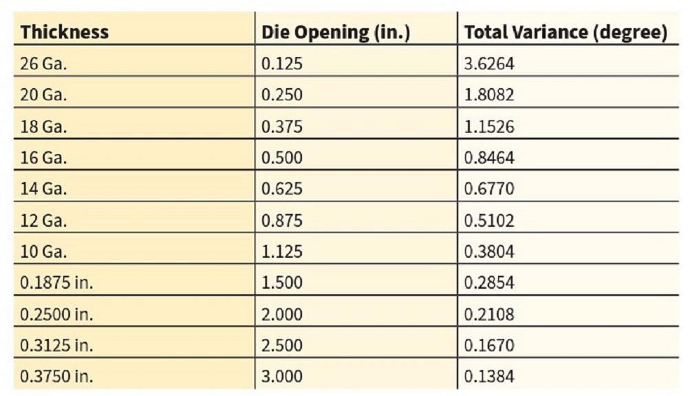
FIGURE 3. As the die opening narrows, part angle variance can grow. These variances, measured for a 90-degree bend, are accurate for 60,000-PSI, low-alloy, cold-rolled steel. Adjustments will be needed for other material types. Note that bend length also plays a role.
About the Author

About the Publication

subscribe now

The Fabricator is North America's leading magazine for the metal forming and fabricating industry. The magazine delivers the news, technical articles, and case histories that enable fabricators to do their jobs more efficiently. The Fabricator has served the industry since 1970.
start your free subscription- Stay connected from anywhere

Easily access valuable industry resources now with full access to the digital edition of The Fabricator.

Easily access valuable industry resources now with full access to the digital edition of The Welder.

Easily access valuable industry resources now with full access to the digital edition of The Tube and Pipe Journal.

Easily access valuable industry resources now with full access to the digital edition of The Fabricator en Español.
- Podcasting

In this episode of The Fabricator Podcast, Caleb Chamberlain, co-founder and CEO of OSH Cut, discusses his company’s...
- Trending Articles
1
Steel industry reacts to Nucor’s new weekly published HRC price

2
How to set a press brake backgauge manually

3
Capturing, recording equipment inspection data for FMEA

4
Are two heads better than one in fiber laser cutting?

5
Hypertherm Associates implements Rapyuta Robotics AMRs in warehouse
