


Predicting an air-formed sheet metal inside bend radius
Fun with the 20 percent rule and minimum bend radius
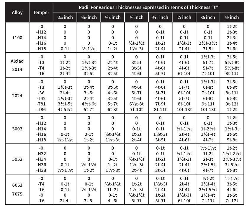
Figure 1
This recommended minimum bend radius chart is for illustrative purposes only. For minimum bend radii information about the material in your shop, consult your material supplier.
Question: My co-workers and I have been reading your columns to help us understand what tooling our shop will need to avoid overstressing our materials with small dies. We air bend our 0.125-inch-thick 5052-H32 aluminum with a 1-mm punch and 16-mm die. Based on your columns, the inside bend radius should be 13 to 15 percent of the die opening. This would make the inside radius 0.094 in. A radius of at least 1.5 times the material thickness is suggested for 5052-H32 to avoid cracking; this means the inside radius is too small. The problem, however, is that I do not get this measurement when I measure the radius.
We switched to a 50-mm (1.968-in.) die, which should produce approximately a 0.295-in. radius, well over the 1.5 times the material thickness recommended for the radius. But instead, we achieved a 0.109-in. radius. Any advice would be greatly appreciated.
Answer: The 20 percent rule is a rule of thumb and, as with all rules of thumb, a little imprecise. Reference a chart from your material supplier and you’ll find the minimum radius increases with thickness, and increases or decreases with the temper of the material.
As you’ve done, fabricators should check with their material supplier for the recommended minimum inside bend radius. But just to illustrate, I’ve included a chart with numbers that reflect the minimum inside bend radius for different alloys and tempers of aluminum (see Figure 1). This chart shows a minimum bend radius of 0 to 1 times the material thickness for 0.125-in.-thick 5052-H32. This is slightly different from the recommendation you have from your aluminum supplier, but that’s no surprise. Variation is expected among different material producers. Regardless, 0 to 1 is a wide range of values, and the variation is amplified by temperature and the natural grain direction within the sheet.
If you refer to information from your material supplier or use a source like matweb.com, you’ll find that the tensile strength of materials varies greatly with temperature. For instance, 5052-H34 aluminum has a tensile strength that varies from 38,000 PSI to 55,000 PSI, all depending on the temperature.
First, here’s a quick review. As a rule of thumb, what does the 20 percent rule state? It states that the radius of sheet metal and plate forms as a percentage of the die opening. The rule’s name comes from stainless steel, which generally forms a radius that’s 20 to 22 percent of the die opening. Mild steel has a lower percentage and, as you pointed out, so does aluminum.
Being a rule of thumb, it’s general, and there’s a range of percentages. The only question is, What is the correct percentage for a given material? That’s a relatively easy question to answer.
Tensile Strength and Sheet Metal Bend Radius
The percentage you use depends on the tensile strength of the material. And again, the higher the temperature, the lower the tensile strength. We may not know the actual temperature of the sheet or even the recommended minimum radius. We have limited control over the direction of the grain in the material. We do have control over the punch and dies, which is a good thing if we make the right decisions.
Again, we need to turn to the tensile strength. According to www.matweb.com, aluminum 5052-H32 has a tensile strength of 33,000 PSI. (As an aside, as you go to higher tempers, you’ll find that the tensile strength increases. 5052-H34 is 38,000 PSI, H36 is 40,000 PSI, and H38 is 42,000 PSI.)
Next we turn to the baseline tensile strength value we use in many of our bending calculations. Our baseline material for the 20 percent rule is 60,000-PSI mild steel, which air-forms a radius that’s about 16 percent of the die opening. This is our starting point.
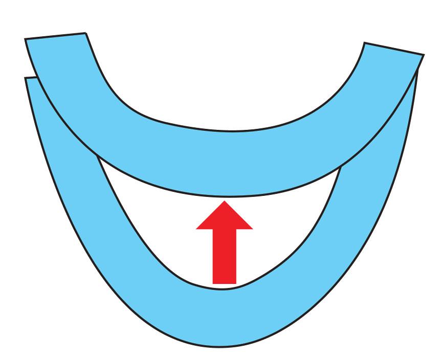
Figure 2
During air forming, a sharp punch nose radius can push the material beyond its naturally floated radius and turn the inside bend radius into a parabola.
To find the correct percentage and predict the inside radius, we need a formula that considers the die width and the tensile strength of the metal:
× Die width] × 0.1 = Inside bend radius
Again, we’re using 60,000-PSI mild steel as a baseline. Actually, the exact material grade of the baseline is irrelevant here; we’re just concerned with the tensile strength.
Considering this, let’s run the equation based on your 33,000-PSI-tensile 5052-H32 aluminum, forming over both the 0.630-in. and 1.968-in. (16- and 50-mm) die openings:
× Die width] × 0.1 = Inside bend radius
[(33,000/60,000) × 0.630] × 0.1 = 0.034 in.
[(33,000/60,000) × 1.968] × 0.1 = 0.109 in.
You didn’t mention the inside bend radius you achieved in your 16-mm die, but my guess is it was right at 0.034 in. For the 50-mm die, you said your resulting inside bend radius was 0.109 in., which is the same value calculated here.
Note that this equation does not address whether the material was bent with or across the natural grain direction. It also doesn’t address the springback factor, or the opening of the inside radius once it’s released from pressure.
Finding the Actual Minimum Bend Radius
Now that we’ve taken the 20 percent rule out of the realm of being just a general rule, let’s take a look at how you can calculate a minimum bend radius accurately.
First, we need to define what it is we’re talking about: A minimum bend radius is the point at which cracks start to appear on the outside surface of the material; that is, the material grains start to separate. We define this as:
As the ratio of the inside bend radius (Ir) to the material thickness (Mt) decreases, the smaller the Ir, and the greater amount of tensile strain on the outside surface of the material. (As an aside, this exemplifies a concept called Poisson’s ratio.) Keep increasing the strain and we eventually get cracks on the outside surface of the bend. The minimum bend radius is given as a multiple of the material thickness—1x, 2x, 3x, and so on.
So where does this minimum bend radius come from, exactly? It’s a calculation based on the relationship between a material’s bendability and something called the tensile reduction of area, which can be found with a standard tensile test or by looking it up in reference materials or on the internet.
The tensile reduction of area (r) is the difference between the material’s original cross section and the smallest cross section as measured at the point of fracture, expressed as a percentage (that is, by what percentage the material area reduced). Conduct a tensile test and calculate for r (or, again, look it up in reference materials), insert that variable into this equation—Minimum Ir = Mt × (50/r -1 )—and you determine the minimum inside bend radius for the material.
Punch Radius Makes a Difference
We’ve discussed the 20 percent rule and minimum bend radius; now let’s look at another kind of minimum bend radius. Go any smaller than this minimum bend radius and your bend turns sharp. For this one, the punch nose radius plays a primary role. If your punch radius is too small, it will crease the center of the bend while still floating a radius based on the 20 percent rule.
What causes this? A narrow punch concentrates significant force over a small area—so much force, in fact, that the punch nose pierces the surface of the material. If your tonnage to form exceeds the tonnage to pierce, you will crease the center of the bend. The smaller the nose radius, the deeper the crease; this in turn increases the bend-to-bend angle variation and amplifies the effects of every material variable, including thickness, hardness, and grain direction. For much more on this, see “What makes an air bend turn sharp on the press brake?” as well as “Minimum versus recommended inside radius,” both archived at www.thefabricator.com.
There’s also the parabolic effect that’s created when using a sharp punch nose. Briefly, when the nose of the punch is too small, as explained previously, it pushes past the natural floated radius. This makes the inside radius take on a parabolic shape during forming. It also results in a radius slightly smaller than would be expected when released from pressure, making the inside radius hard to measure (see Figure 2). For more on this topic, check out the “Grand unifying theory of bending on a press brake” series, published September through December 2015 in The FABRICATOR, and archived on thefabricator.com.
Variables in the Sheet Metal Bend Radius
As you can see, a lot goes into predicting an inside bend radius. But if you know your material’s tensile strength and choose an appropriate punch tip and die opening, you should find success. Once you know how to perform the calculations, even a rule of thumb can be precisely applied.
Steve Benson is a member and former chair of the Precision Sheet Metal Technology Council of the Fabricators & Manufacturers Association International®. He is the president of ASMA LLC, steve@theartofpressbrake.com. The author’s latest book, Bending Basics, is now available at the FMA bookstore, www.fmamfg.org/store.
About the Author

About the Publication

subscribe now

The Fabricator is North America's leading magazine for the metal forming and fabricating industry. The magazine delivers the news, technical articles, and case histories that enable fabricators to do their jobs more efficiently. The Fabricator has served the industry since 1970.
start your free subscription- Stay connected from anywhere

Easily access valuable industry resources now with full access to the digital edition of The Fabricator.

Easily access valuable industry resources now with full access to the digital edition of The Welder.

Easily access valuable industry resources now with full access to the digital edition of The Tube and Pipe Journal.

Easily access valuable industry resources now with full access to the digital edition of The Fabricator en Español.
- Podcasting

In this episode of The Fabricator Podcast, Caleb Chamberlain, co-founder and CEO of OSH Cut, discusses his company’s...
- Trending Articles
1
AI, machine learning, and the future of metal fabrication

2
Employee ownership: The best way to ensure engagement

3
Dynamic Metal blossoms with each passing year

4
Steel industry reacts to Nucor’s new weekly published HRC price

5
Metal fabrication management: A guide for new supervisors
