


Press brake bending and notching: A symbiotic relationship
The type of square corner notch directly affects layout dimensions and bending order
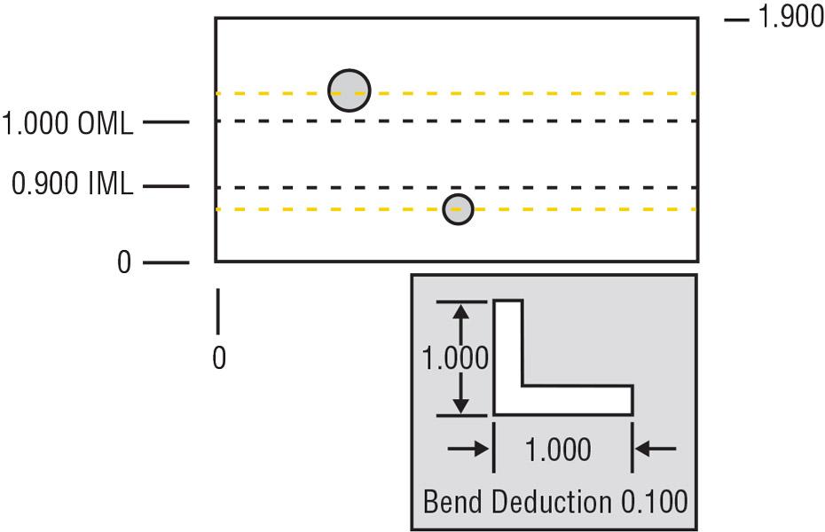
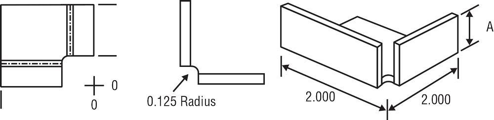
Figure 1
The area between outside mold line (OML) and inside mold line (IML) represents where the radius will form. The yellow lines represent the same bend but with a larger radius and, therefore, a larger area between the mold lines.
Question: I have read many of your articles over the years. In all that time I do not remember you discussing corner notching. I lay out, notch, and form sheet metal trays, boxes, and a few plate parts. My problem is I do not have access to a CAD system. While I can find quite a few books on sheet metal pattern layout, I can find little to nothing on the topic of precision corner notching for sheet metal.
Can you offer any guidance or help me locate reference materials?
Answer: If you want to build high-quality sheet metal parts, you are not just required to ensure the final forming and dimensions are correct and held to tolerance. To produce the various parts a job shop requires, you need to know about notches, why they are necessary, their various kinds, and which is appropriate to use.
This begins by calculating the correct bend deduction (BD)—for a review of this, see previous Bending Basics articles archived on thefabricator.com. If you have calculated those numbers accurately, based on the actual inside radius that will be produced, you will be able to accurately lay out a corner notch style of your choice, one that will close tightly, or at least to the required dimension, without binding or pinching. This too is greatly affected by forming order—that is, the order in which you sequence your bends.
CAD Versus Manual Layout
Fewer and fewer people actually perform their own notching layouts now. Even the heating and air conditioning (HVAC) community is moving toward computer-aided design and manufacturing. CAD/CAM has become almost universal.
Nonetheless, learning the background of laying out precise notching will help you to understand what your CAD system is doing. This will assist you with selecting the correct corner joint and assigning the forming order to the work traveler or offline program. There is no doubt this knowledge will help you with your job, especially if you are performing prototype work.
So Many Styles
Four basic 90-degree-corner types are the 100 percent weld notch, 50 percent weld notch, closed notch, and relieved notch. These are your straightforward perpendicular corners. Each style has a specific purpose.
The 100 and 50 percent notches are similar, the differences being the strength of the corner weld. While the forming order isn’t an issue with a 100 percent weld notch, the forming order is an issue with the 50 percent weld notch.
The relieved notch offers clearance in the corner, and it’s often designed into a part so that the corner itself can mate on the inside of another square corner—to a shelf, for example.
The Mold Line
First, you need to make sure you’re using the right mold line. The area between the mold lines represents where the part radius will be. If your BD and calculated radius match the actual radius you achieve in the workpiece, the area defined by the mold lines will be accurate.
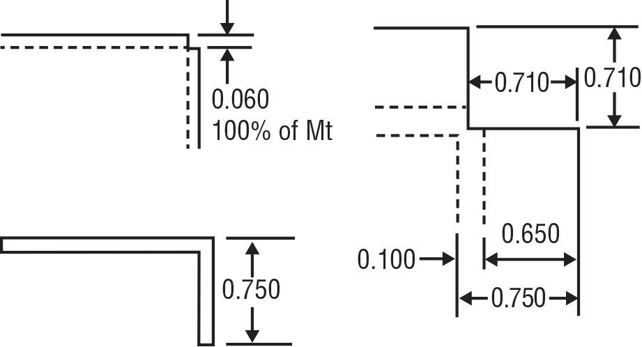
Figure 2
This shows a 100 percent weld notch calculated in 0.060-in.-thick material with a 0.750-in. outside flange dimension and a bend deduction of 0.100 in.: (0.750 – 0.100) + 0.060 = 0.710 in.
To find the mold line locations, we begin with the outside dimension for the outside mold line (OML). Say you have a workpiece that’s 2 in. long and the outside flange dimension is 1.000 in. So here the OML would be at 1 in., as shown in Figure 1. We find the inside mold line (IML) by removing the BD. In Figure 1, the BD is 0.100 in., so the IML is located at 0.900 in. (1.000 – 0.100).
Technically, any change in the bend radius area would occur toward the IML location. In the real world of press brake operation, however, the operator will center the bend line to split the error between the two planes, using the tolerance of a given feature.
If you calculate your inside radius incorrectly or you fail to achieve the inside radius as planned, the area defined by the mold lines will also change. This in turn may mean that some features will be near or within the bend radius itself, which can cause distortion. For instance, as shown by the yellow lines in Figure 1, increasing the radius increases the area between the mold lines; this in turn causes holes to become located on the radius. Feature distortion will be the result.
The 100 Percent Weld Notch
The simplest form of notch to lay out, the 100 percent weld notch is also the strongest and most common. It’s where the two inside corners on the material meet at right angles; if welded, the notch would be filled to 100 percent of the material thickness. To calculate this, we subtract the bend deduction from the outside flange dimension, then add the material thickness (see Figure 2).
The 100 percent notch is often defaulted to in CAD/CAM programs, and it requires no special forming order. It’s just that simple. This is because, after overbending slightly to account for springback, either flange will freely pass by the previously formed flange.
The 50 Percent Weld Notch
The 50 percent notch is similar to the 100 percent notch, except that it’s only half of the material thickness (see Figure 3). You need to determine which axis, or flange, will be on the outside.
To calculate the 50 percent weld notch for one axis, subtract the BD from the outside flange dimension and add the material thickness, as before. For the second axis, you also subtract the BD from the outside flange dimension, but this time you add only half the material thickness.
The 50 percent notch requires some forethought about springback and the clearance necessary for one bend to pass freely by the previously formed flange. Forming order makes a difference, as the flange with the smaller notch dimension will need to be formed first. If it’s formed second, it will collide with the adjacent flange.
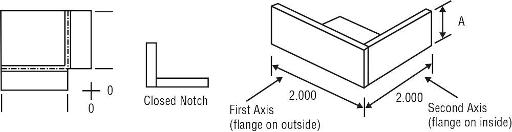
The Closed Notch
The closed notch is illustrated in Figure 4. To calculate the closed notch for the first axis, you subtract the BD from the outside flange dimension and add the material thickness. For the second axis, just subtract the BD from the outside flange dimension.
Forming order makes a difference here, too, as the flange with the smaller notch dimension will need to be formed first to avoid a collision with the other flange. In other words, the flange that goes to the inside forms last.
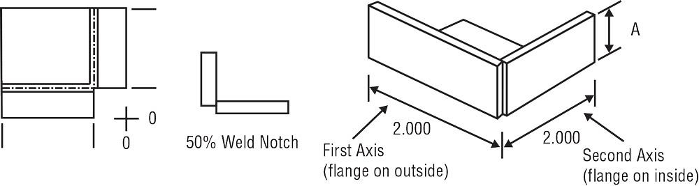
Figure 3
Calculate the dimensions of the 50 percent weld notch as follows: First axis = (Outside flange length – BD) + Material thickness; Second axis = (Outside flange length – BD) + (Material thickness/2).
The Relieved Notch
This type of notch builds clearance into the corner, such as what you might find in the corner of a shelf where a sharp square corner could cause mounting problems (see Figure 5). In this notch, the flanges never touch. Calculating this is the same as for calculating the 100 percent weld notch, except that you add the dimension of the relief.
Relieving the Corners
Except for the relieved notch, the other three notch styles may require a relief hole to stop the material from tearing in the corners. Be sure to center the hole’s diameter directly over the crosshairs created at the intersection of the two notch edge centers.
Try to use a hole diameter that is between the material thickness and the BD values—the closer to the material thickness, the better. Please note that whether you are using a CAD system or laying out and punching by hand, be sure to drill or punch the relief hole into location before the notch is added. This keeps the die and punch from side loading and damaging the punch or the part.
Conclusion
With a little practice you will be able to lay out, notch, and form square corner notches. Whether you are a press brake technician or are programming in CAD, an understanding of the notching will lead to better products and a more efficient operation. As for reference material, I would recommend my latest textbook, The Art of Press Brake, the details of which are given at the end of the article.
Next month we’ll delve deeper into notching and forming order and take a brief look at more advanced layout concepts, including perpendicular flanging, double bends, compound corners, and internal corner flanging.
Steve Benson is a member and former chair of the Precision Sheet Metal Technology Council of the Fabricators & Manufacturers Association International®. He is the president of ASMA LLC, 2952 Doaks Ferry Road NW, Salem, OR 97301, steve@theartofpressbrake.com. Benson also conducts FMA’s Precision Press Brake Certificate Program, which is held at locations across the country. For more information, visit www.fmanet.org/training, or call 888-394-4362. For more information on bending, check out Benson’s book, The Art of Press Brake: the Digital Handbook for Precision Sheet Metal Fabrication, © 2014, available at www.theartofpressbrake.com.
About the Author

About the Publication

subscribe now

The Fabricator is North America's leading magazine for the metal forming and fabricating industry. The magazine delivers the news, technical articles, and case histories that enable fabricators to do their jobs more efficiently. The Fabricator has served the industry since 1970.
start your free subscription- Stay connected from anywhere

Easily access valuable industry resources now with full access to the digital edition of The Fabricator.

Easily access valuable industry resources now with full access to the digital edition of The Welder.

Easily access valuable industry resources now with full access to the digital edition of The Tube and Pipe Journal.

Easily access valuable industry resources now with full access to the digital edition of The Fabricator en Español.
- Podcasting

In this episode of The Fabricator Podcast, Caleb Chamberlain, co-founder and CEO of OSH Cut, discusses his company’s...
- Trending Articles
1
How to set a press brake backgauge manually

2
Capturing, recording equipment inspection data for FMEA

3
Tips for creating sheet metal tubes with perforations

4
Are two heads better than one in fiber laser cutting?

5
Hypertherm Associates implements Rapyuta Robotics AMRs in warehouse
