


Contributing editor
IDOT issued a challenge for the development of a viable, economical solution to accelerate the replacement of the aging bridge infrastructure in the U.S. An industry task group developed press brake-formed tub girders for short-span bridges that are formed in a factory, preassembled with a concrete platform, and installed on-site in hours or days.
Editor’s Note: This article is based in part on a presentation at the 2019 AISC World Steel Bridge Symposium, St. Louis, April 3, 2019.
It’s no secret that America’s infrastructure is due for a replacement. When the I-35 Mississippi River Bridge in Minneapolis collapsed in 2007, killing 13 people, the whole country took notice.
Two years later the American Recovery and Reinvestment Act included nearly $50 billion in funding for transportation infrastructure to support needed repairs and long-term transformative investments in communities across every state. Infrastructure repair and replacement is one goal that both political parties seem to agree on.
According to the Bureau of Transportation Statistics, there were more than 617, 000 bridges in 2019 in the U.S. and only 279,582—44%—are in good condition. More than 56,000—9.1%—of the nation’s bridges were categorized as structurally deficient in 2016.*
Time is of the essence. Almost four in 10 are 50 years or older, according to the American Society of Civil Engineers (ASCE) 2017 statement.
Chief Economist Dr. Alison Premo Black of the American Road & Transportation Builders Association (ARTBA) said, “At the current pace, it would take more than 50 years to repair America’s structurally deficient bridges.”
“The greatest need is in the short-span category of 140 ft. or less,” said Dr. Karl Barth, West Virginia University, Dept. of Civil and Environmental Engineering, adding that nearly half of structurally deficient bridges fall in the short-span category. A short-span bridge is defined as a bridge that is the distance between two intermediate supports shorter than 140 ft.
Seeking new, better, faster, cheaper ways of replacing bridges to help address the U.S. infrastructure crisis, IDOT issued a challenge for the development of a viable, economical solution to replacing the aging bridge infrastructure for short-span structures of up to 80 ft.
Barth headed the industry task group responsible for developing the technology.
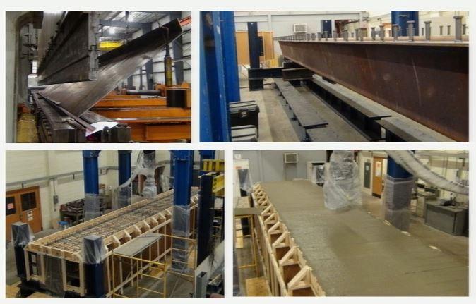
West Virginia University researchers began with the form of a typical welded trapezoidal box but fabricated it via press brake bending to save cost and time. Fabrication was performed by Greiner Industries. Photo courtesy of the Short Span Bridge Alliance.
We were tasked by the federal highway department to develop systems for the acceleration of short-span bridge construction that would be economical,” Barth said. “The goal was to use standard, commonly available plate widths of 84 in., 96 in., and so forth.” The process also had to be compatible with mass production to avoid the costs of customization.
What is the system? It’s simply a straightforward steel tub girder with a precast concrete deck—with a twist.
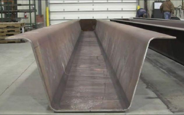
“We wound up with a standard steel trapezoidal box but we fabricated it from press brake bending rather than conventional welding,” Barth said. “Features for the short-span can be produced in about 30 to 40 minutes using press brake forming.”
The girder type is the common U.S. trapezoidal girder slope ratio of 1-4 on the edges, with a 5T bend radius, Barth explained. “We figured we didn’t need much compression on the flange. We held them at 6 in. wide. We just needed enough to hold the studs until we got the deck on there.”
The press brake-formed plate tub girder (PBFTG) is galvanized to extend life and is then topped with a concrete deck. “Our standard is to hot-dip galvanize them inside and out to provide 60-plus years of protection.
“It’s not hugely innovative. But it’s made in a means that can be economical in the short-span market. Bigger, more complicated bridge geometries with closed sectioned tubs have a very ideal geometry for welding applications. The problem is that you can’t scale that technology down economically to the 40-, 60-, 80-ft. short-span bridge market,” Barth concluded.
The module can be preassembled or field-assembled. Modules are joined using ultrahigh-performance concrete (UHPC) longitudinal closure pours.
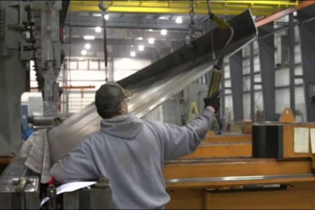
During the research phase, the press brake bending was performed by Greiner Industries, Mount Joy, Pa. The fabricator formed the tub’s bends on a 2,750-ton, 40-ft.-long Baykal brake press, which it already had, and then purchased extension tooling for the job.

Greiner Industries, Mount Joy, Pa. The fabricator formed the tub’s bends on a 2,750-ton, 40-ft.-long Baykal brake press. The fabricator also installed a laser light alignment tool that points to the interior bend target to ensure that the piece was completely aligned with the punches.
The manufacturer also has a 26-ft. and 34-ft. brake that can be used together to bend 60 ft. of ¾-in.-thick plate, but it used the 40-footer because it offered a number of advantages for the 40-ft. bridge span.
The bed opening can be adjusted from 3 to 17 in. “We can bend up to 1-1/4-in.-thick plate the whole 40 ft.,” relayed Rolling and Forming Division Manager Bruce Sine. “Because it’s a single machine, we have the whole press available.”
The press brake also accommodated the multiple bends required to form the tub. “Once you get into multiple bends it gets interesting, because if you have flanges, you have to flip it over to bend those, and you have to have enough room to be able to get to the second bend without hitting anything else,” Sine said. “When you use tandem presses, depending on the throat of it, it can hit the back frame, so you wouldn’t be able to bend long legs on it. With the 40-footer, we have 2 ft. of clearance, so we have plenty of clearance to bend the flanges.
“Having a single press brake with the tonnage that we had was an advantage,” Sine said.
Greiner also installed a laser light alignment tool that points to the interior bend target. “We wanted to make sure that the piece was completely aligned with the punches. That way you have a true measurement as to where you want to bend. It’s a lot more precise than a tape measure.”
The press brake is equipped with mechanical crowning adjustments in the bed of the machine. “Crowning’s not a problem; you just adjust the bed for that and it comes out pretty nice. And you actually can adjust the Y1 and Y2 axis if one side is hitting harder than the other.”
Sine said that overall, the job was not too hard. “Once it was dialed in, it went rather easily.”
The research team performed extensive fatigue testing of the girders to compute their yield capacities at various plate thicknesses. The team used an 84-in.-wide by 7/16-in. plate (50- and 79-KSI) steel for a host of tests for research at the university. “That is the biggest girder we could build and test to failure with our 330-kp actuator to evaluate load-carrying capacity,” Barth said.
The testing showed the “sweet spot” at each plate thickness (7/16 in., ½ in., 5/8 in.) and widths (60 in. through 120 in. long). The depths they finalized on are the depths of the girder superstructure after validating the capacity of the girders. For spans up to 60 ft., ½-in. plate works. For longer spans up to 80 ft., 5/8-in.-thick plate is required.
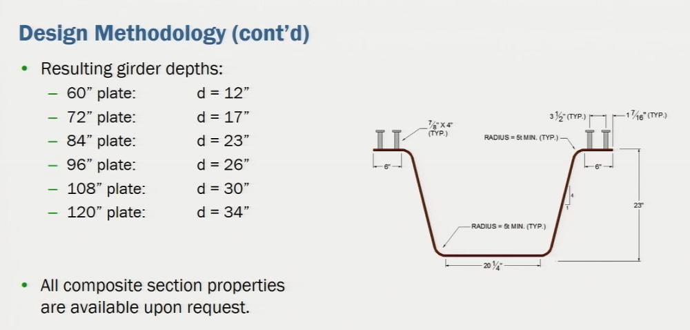
Testing showed the sweet spot at each plate thickness and width for girder depths.
“There is one depth at which you could get the maximum capacity for that section. Once you set that flange width and the slope ratio and pick your depth on a common mill steel plate, all the geometry comes out of that,” he said.
The team tested the fatigue performance of both galvanized and uncoated steel sections to see if problems would occur with the bend radii selected. Then they tested the modular system with closure pour to evaluate the deck. They evaluated the modules’ capacity with a cast-and-place deck system and bracing requirements and deflection. “We’ve been testing this for seven years. So this system has been thoroughly vetted,” Barth said.
The PBFTG meets the American Association of State Highway and Transportation Officials (AASHTO) requirements.
A grant from the U.S. Dept. of Transportation Federal Highway Administration’s (FHWA) Innovative Bridge Research and Deployment (IBRD) Program laid the groundwork to complete the first installation of the modular PBFTG system in the U.S.
The FHWA awarded engineer Brian Keierleber, PE, $350,000 from the IBRD program to replace the Amish Sawmill Bridge in Fairbank Township, Buchanan County, Iowa.
“Standardization was significant in the short-span market,” Keierleber said. “We don’t want to custom-design each one as a work of art. If you need a 40-ft. girder, you want to just go to this table and pick this girder that spans 36 ft. There is no reason to redesign it.” Standard designs are from 20 to 80 ft.
The bridge construction began in late summer 2015 and was completed in December 2015.
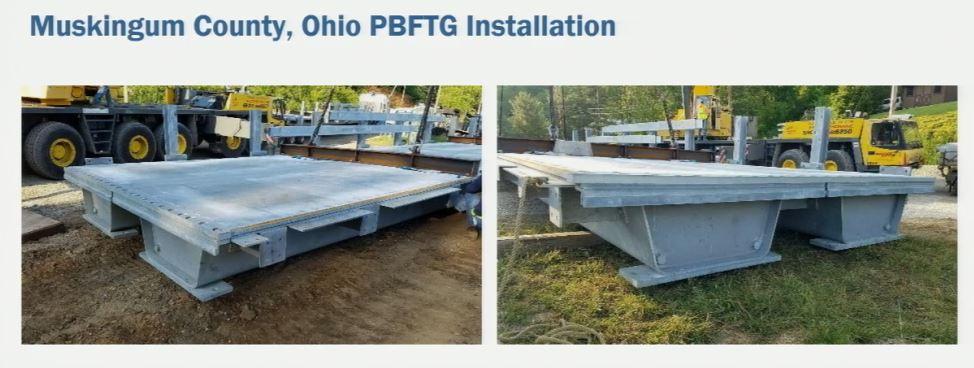
A bridge in Muskingum County, Ohio, needed to be replaced.
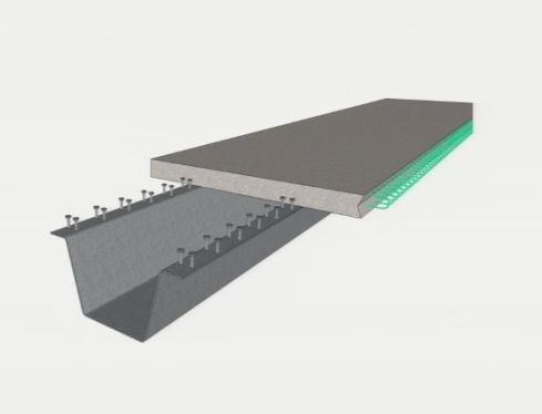
The PBFTG can be formed flange-out flange-in as a shallow box.
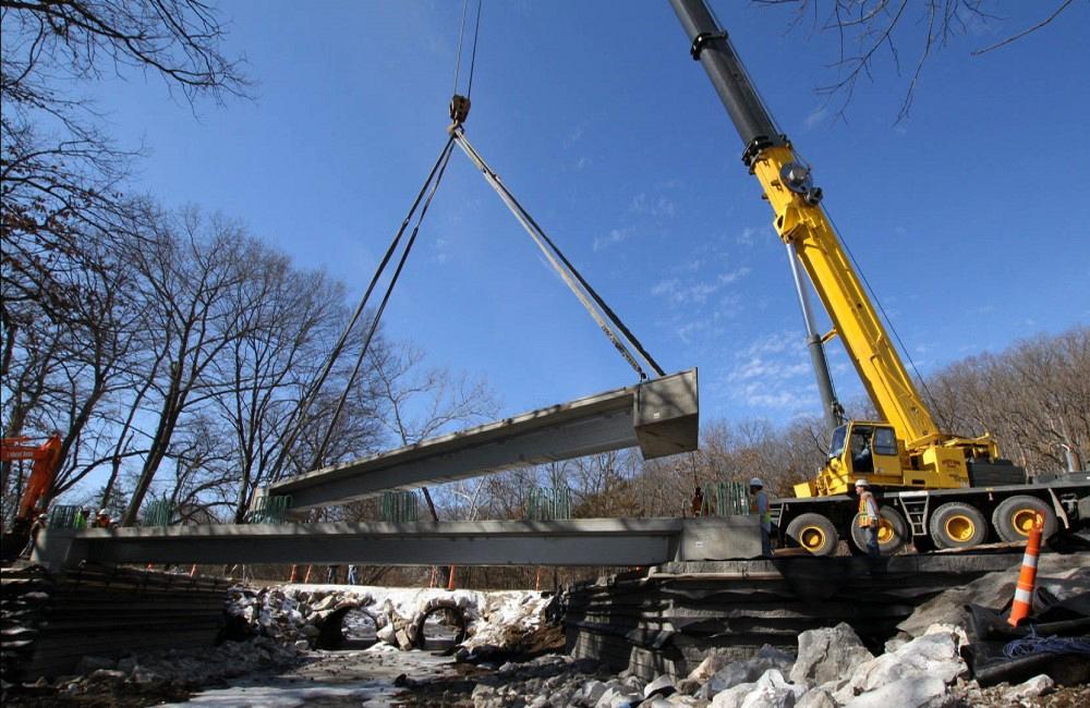
The sandwich plate deck was assembled off-site and modular girders arrived at the site on one truck.
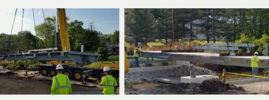
“We talk about accelerated construction. The superstructure was installed in 20 minutes. I had never seen a 20-minute bridge go in before,” Barth said.
St. Clair County, Mich., maintains 226 bridges. Of those, 20 are in critical or serious condition, 21 are in poor condition, and two have weight limits prohibiting truck traffic. Two were closed to traffic because of their condition. “They cannot keep up. This is common throughout the U.S.,” Barth said.
Two bridges in St. Clair County had weight restrictions prohibiting truck passage. The two-lane road with more than 16,000 crossings is a critical path into Marine City. They were built in 1953 and had given 65 years of service. No recoating of steel beams or other maintenance had been performed on them.
TEG Engineering was hired to engineer replacements for the two bridge superstructures in summer 2018. The company designs prefabricated bridges to help minimize mobility impacts that result from on-site construction activities.
“The bridge girders needed to be simple, durable, AASHTO design-compatible, and sustainable,” said Guy Nelson, PE, TEG Engineering. “If these were all one-offs, you’re never going to get a system that is affordable. We had to implement affordable tub girders. And we’re doing that throughout the U.S.”
Cost comparisons showed a conventional steel bridge with hot mix asphalt (HMA) overlay using galvanized steel decking would cost $75,000; a precast box culvert system would cost $63,000; and the PBFTG system HMA approaches came in at $57,000 and the shortest road closure duration.
“We sourced the fabricated press brake formed steel tub girder, the galvanizing, and the studs and hired a local qualified precaster to assemble the whole bridge,” Nelson said. Fabrication of the PBFTG—galvanizing, metal fabrication, and concrete deck pours—takes about two months, so it began two months prior to the bridge demolition.
On one of the bridges, the county was able to use its own excavator equipment to install the 35-ft.-span units for the bridge and needed only a crane to install a 45-ft. span on the second bridge.
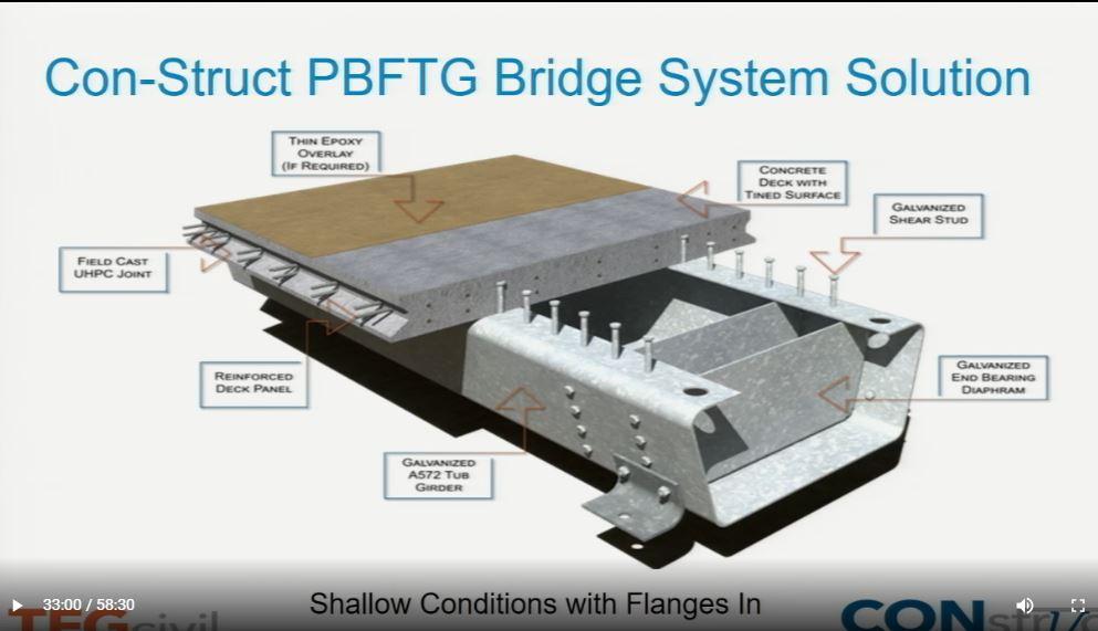
The flange-in box has a wider bottom flange to increase the capacity and stiffness of the whole system when deflection is a problem or a shallower box is needed to match the previous system.
The superstructure replacement was completed in four days. It took two days to demolish the existing bridge and another day to repair concrete abutments. The PBFTG superstructure itself was installed on the fourth day in four hours. “The girders were brought in at 8 a.m. and assembled on-site by noon,” Nelson said.
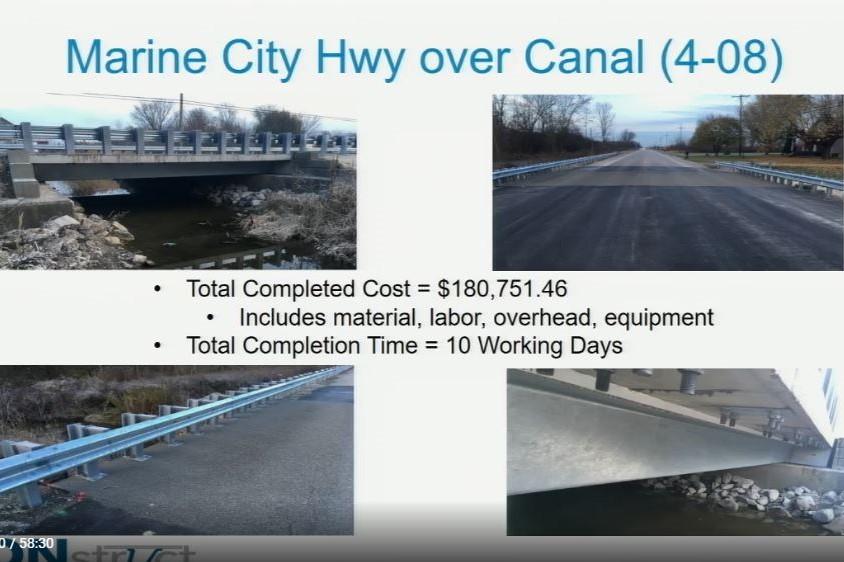
A polymer concrete was poured for the deck joint, followed by an epoxy overlay. Then an asphalt layer topped the entire deck. Guardrails were installed last. The total completion time was 10 working days.
The total final cost was $180,751 including materials, labor, overhead, and equipment.
*The term “structurally deficient” was redefined in 2018, and now 5.5% of U.S. bridges classified as structurally deficient. In addition, the agency no longer tracks bridges previously termed “functionally obsolete.”

The Fabricator is North America's leading magazine for the metal forming and fabricating industry. The magazine delivers the news, technical articles, and case histories that enable fabricators to do their jobs more efficiently. The Fabricator has served the industry since 1970.
start your free subscription
Easily access valuable industry resources now with full access to the digital edition of The Fabricator.

Easily access valuable industry resources now with full access to the digital edition of The Welder.

Easily access valuable industry resources now with full access to the digital edition of The Tube and Pipe Journal.

Easily access valuable industry resources now with full access to the digital edition of The Fabricator en Español.
In this episode of The Fabricator Podcast, Caleb Chamberlain, co-founder and CEO of OSH Cut, discusses his company’s...


