


Press brake questions from around the world
Addressing tonnage calculations, tool selection, and k-factors for press brake operators
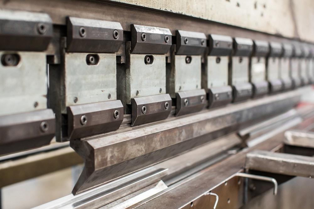
Press brake guru Steve Benson answers a list of reader questions from Germany, Africa, and beyond. Getty Images
I’ve received so many questions over the years, I haven’t been able to respond to all of them. If any of you have been waiting for a reply, I apologize for the delay.
Questions come from people in the U.S. and Canada, of course, but also from all over the world, including India, Europe, and Africa. The FABRICATOR might be published in the U.S., but thanks to the web, it has a global audience. After all, the physics behind sheet metal don’t change no matter where a shop operates. So without further ado, on to the questions!
Proper Die Opening and Tonnage in Nigeria
Question: I’m a press brake operator in Nigeria, and I read some of your articles in The FABRICATOR magazine with great interest. I usually run into bottlenecks when trying to calculate tonnage and selecting tools. Is there an easy way to go about my tonnage calculations and tool selection?
Answer:The tonnage calculations are simple. Note that these calculations use units commonly used in the U.S., including U.S. tons and imperial units: [575 × (Material thickness)2] / Die opening / 12 = Tonnage per inch for mild steel.
Next, you need to factor that value by the forming method, material type, and the length of bend. Regarding the bending method, air forming has a factor of 1.0, bottoming has a factor of 5.0, and coining has a factor of 10.
For the material factor, you need to find the tensile strength for the material you’re bending, then compare that value to our baseline material, which is 60,000-PSI-tensile cold-rolled mild steel. For example, if your current material has a tensile strength of 120,000 PSI, your material factor will be 2 (120,000/60,000). If you can’t find your material’s tensile strength, you can refer to the chart in Figure 1.
The length of bend is the total number of inches being formed, not the entire length of the tooling. Considering all these factors, the complete tonnage formula looks like this:{[575 × (Material thickness)2] / Die opening / 12} × Bend length × Material factor × Method factor
Now it’s on to your tool selection. For a comprehensive breakdown, check out the final article of the Grand unifying theory of bending series from December 2015. But for now, here’s a quick summary.
For small die openings, multiply the outside radius by 3.429. This formula will give you a geometrically perfect die opening, which no doubt is not available. Select the tool you have that is closest to perfect and use that if you don’t exceed the tonnage limits of the machine or tooling.
For large-radius bends, select your dies in the following way:
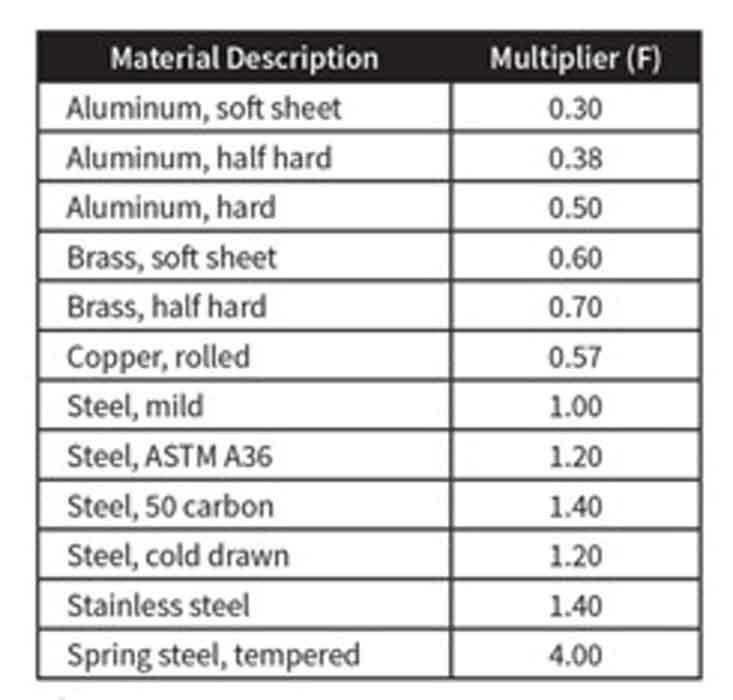
Figure 1 Material factors are multipliers used in tonnage calculations to adjust for different tensile strengths.
Standard V die = 2.5 × (Material thickness + Inside radius)
Relieved die = 2.2 × (Material thickness + Inside radius)
Tooling Advice in Canada
Question: I want to start an electrical panel production company. We want a fully automated CNC press brake for working with at most 6 mm thickness and 3 meters long. Which press brake tooling do you suggest?
Answer: Knowing how electrical panels can change and are usually toleranced rather tightly, I recommend precision-ground press brake tooling.
It may be more expensive, but the cost of the tooling will pay for itself in labor savings and give you much greater versatility with your setup.
However, be aware of the tooling naming conventions out there. For example, I wouldn’t purchase precision planer tooling as it will have the same issues that all planer tooling has; it just comes in a precision-ground profile. It might look like the real deal, but it really isn’t.
Good luck starting your own business. It will be worth it.
Sharp Bends From Germany
Question: I’m from Germany and read your articles about bending with high interest. I have a question about k-factors and measuring the inside bend radius. We form 2-mm (0.078-in.) 304 stainless steel over a 12-mm (0.472-in.) V die, and we use a 0.6-mm (0.023-in.) punch radius. Practically speaking, these tools don’t create a radius, but instead a “fold.” How do I measure this, exactly? I have built various formulas into an Excel sheet, but my results don’t seem to be accurate.
Answer: With the description you have given, I believe that the root cause of the issues you are encountering relate to forming with a sharp-bend relationship between the punch radius, material thickness, die opening, and applied tonnage.
A sharp bend elongates the radius to a parabolic shape and makes an accurate radius measurement hard to perform and difficult if not impossible to predict. And by extension, this makes the value for the k-factor hard to predict with any accuracy. The physical limitations of the metal make it challenging to accomplish a bend radius less than material thickness without coining or bottoming the sheet metal.
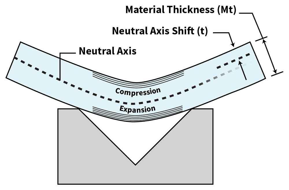
Figure 2 When you bend sheet metal, the neutral axis shifts toward the inside surface of the bend. The k-factor is the ratio of the neutral axis location (t) to the material thickness (Mt).
The material within the bend goes through a few changes. It expands on the outside radius and compresses on the inside radius. The compression cannot exceed the expansion, which means the maximum k-factor cannot be greater than 0.50.
Here’s another way to think about it. A bend’s neutral axis is an area where there is neither compression nor expansion of the material. During bending, that axis shifts toward the inside surface of the bend. A k-factor is the ratio that represents how much that neutral axis shifted during bending: The smaller the k-factor value, the more significant the shift (see Figure 2).
For much more detail, check out “Analyzing the k-factor in sheet metal bending,” a two-part series that ran in the September and October 2018 FABRICATOR. When you’re there, you can also look up “Predicting the inside bend radius when bending with a press brake,” along with “A grand unifying theory of bending on a press brake,” a four-part series that ran in 2015. You might also wish to review “How to calculate the air formed radius of different bend angles.”
In all this you’ll find various ways to calculate the inside bend radius as well as the k-factor. Again, if you’re bending sharp, your operation won’t be consistent, so predicting the k-factor can be next to impossible. For more detail on how to avoid a sharp bend, check out Taking a deep dive into press brake tonnage, a two-part series from 2019.
The bend allowance formula that I’ve used in this column for years incorporates an average k-factor of 0.446, which gets you close enough for many applications. To get a little closer, you can refer to generic k-factor charts, like the one in Figure 3. And to get really close, you can measure some test pieces and run the calculations, as described in the k-factor series that ran in September and October of 2018. Those articles even delve into y-factors, which many modern bending software packages use.
For a little more insight on the k-factor, check out Figure 4, a chart that shows how the k-factor changes as the inside-radius-to-material-thickness relationship changes. The blue line segment shows where the inside bend radius is less than the material thickness. From there, the k-factor increases (gold line) until it reaches 0.5.
This chart shows the background behind another method to calculate k-factors. Again, this is just an estimation, but one that can be extremely useful if it gets you close enough for your product mix.
If we study Figure 4, we see that the chart gives us a k-factor of 0.27324 where the blue line stops and the gold line starts. The gold line starts there and slopes up until the bend radius is four times material thickness. At that point, the chart gives us a k-factor of 0.5—for all practical purposes, the maximum k-factor you can have.
The number at the end of the blue line, 0.27324, is our minimum k-factor that we achieve under perfect conditions. We can express this mathematically with the following formula: Minimum k-factor for air bending under perfect conditions = (4.0 – pi)/pi. Under that gold line, the k-factor changes by 0.22676. How do we know this? We simply subtract the minimum k-factor from the maximum k-factor of 0.5 (0.5 – 0.27324 = 0.22676).
Note how the gold line slopes upward over three sections on the chart—between 1 and 2, between 2 and 3, and between 3 and 4. To calculate how much the k-factor changed within one segment, we divide 0.22676 by 3 to get 0.075586. Once we have this, we approximate the k-factor by plugging this value into the following equation: k-factor = 0.075586 × [(Inside radius/Material thickness) – 1] + 0.27324. So for a material thickness of 0.062 in. and an inside radius of 0.093 in., we would have a k-factor of 0.311. Again, this is just an approximation—a tool in your k-factor toolbox, so to speak. If the tool works for you, you can insert this equation into software like Excel and let the calculator do the work for you.
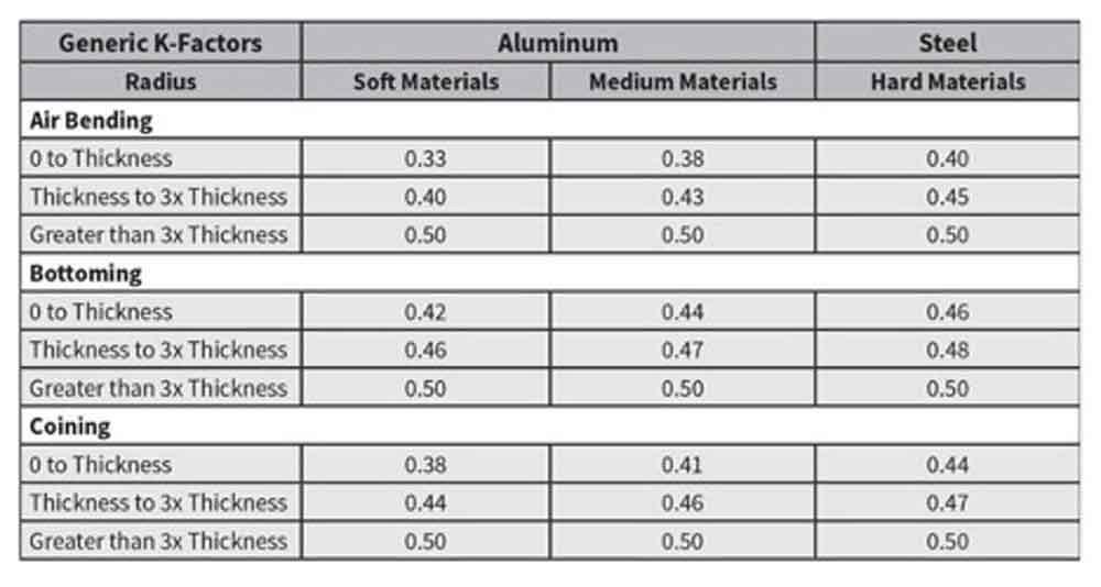
Figure 3 You can run test pieces to calculate a specific k-factor, or you can refer to a chart such as this one.
Speaking of calculators, a few are available on my website, theartofpressbrake.com. It has the sharp bend calculator, the minimum bend radius calculator, the springback calculator, and, finally, the k-factor calculator. After you sign up, you can access these calculators for free.
Tool Angles From Canada
Question: I’ll jump right into it. In a previous article I noticed you “yelled” at the gentleman using a 90-degree punch with an acute die. We end up doing the same thing in my shop from time to time, usually on a press brake that will not allow us to exceed input tonnage limits. Are we at risk while using this machine, assuming all data is entered correctly into the controller?
Answer: The short answer is Yes! Why? Because the tools are not designed to be stressed in that manner. You’ll be applying force in ways and places that can and will cause the tooling to overload and break.
Also, years ago precision-ground tooling was through-hardened to a very high Rockwell number. This added tool life; they lasted forever if they weren’t abused. But when these older precision-ground tools are overloaded with tonnage, and in ways the tonnage was not intended to be applied, they could explode and in many cases throw shrapnel a very long way. If it were me, I wouldn’t do it. Get the correct tooling and perform the operation safely!
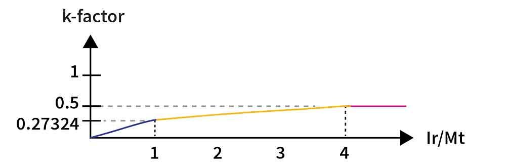
Figure 4 This chart shows how the k-factor increases with the inside-radius-to-material-thickness relationship.
About the Author

About the Publication

subscribe now

The Fabricator is North America's leading magazine for the metal forming and fabricating industry. The magazine delivers the news, technical articles, and case histories that enable fabricators to do their jobs more efficiently. The Fabricator has served the industry since 1970.
start your free subscription- Stay connected from anywhere

Easily access valuable industry resources now with full access to the digital edition of The Fabricator.

Easily access valuable industry resources now with full access to the digital edition of The Welder.

Easily access valuable industry resources now with full access to the digital edition of The Tube and Pipe Journal.

Easily access valuable industry resources now with full access to the digital edition of The Fabricator en Español.
- Podcasting

In this episode of The Fabricator Podcast, Caleb Chamberlain, co-founder and CEO of OSH Cut, discusses his company’s...
- Trending Articles
1
AI, machine learning, and the future of metal fabrication

2
Employee ownership: The best way to ensure engagement

3
Steel industry reacts to Nucor’s new weekly published HRC price

4
How to set a press brake backgauge manually

5
Capturing, recording equipment inspection data for FMEA
