


Senior Editor
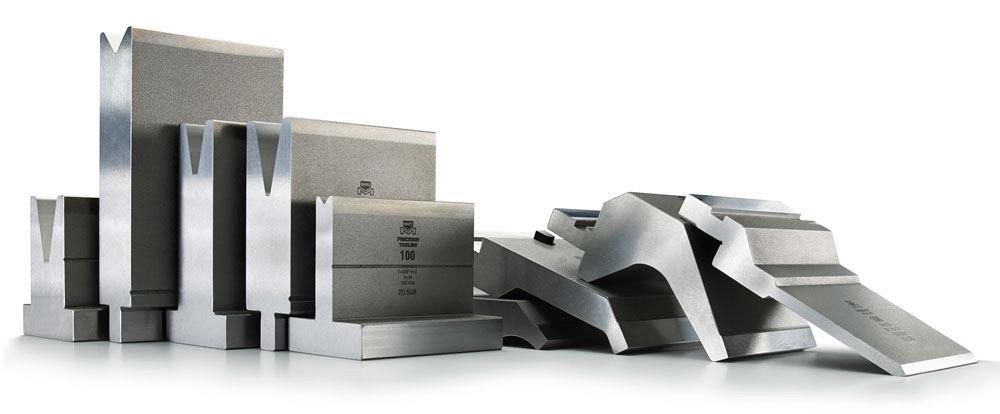
Precision-ground tools on modern press brakes can make a bending operation extremely consistent. But tolerances still must take material variations into account. Photo courtesy of Mate Precision Tooling.
To the uninitiated, sheet metal and plate bending looks simple enough, but the truth is that it’s often the most complicated process on many metal fabrication shop floors. Theoretically, it shouldn’t be complicated. The science of sheet metal bending has proven formulas for bend allowances and bend deductions that account for material elongation for given materials. Why then do press brake operators still have so many tryout parts? Why can’t bending be simpler?
Well, it can be—with realistic tolerancing.
That was the conclusion of an engaged discussion at a Chicago steakhouse in November of last year. On one side of the table sat Steve Benson, president of Salem, Ore.-based ASMA LLC. Benson is a well-known press brake expert and columnist for this magazine. On the other side of the table was Larry Boden, press brake tooling product training specialist at Anoka, Minn.-based Mate Precision Tooling.
“We had a lengthy discussion of sheet metal manufacturing and the standard misuse of tolerancing,” Benson recalled, adding that realistic tolerancing remains one of the easiest, most practical paths to efficient bending.
The accuracy and repeatability of modern press brakes and precision-ground tooling have helped make bending a lot faster and more predictable than it used to be. Still, one huge variable remains: the sheet metal itself.
As Boden explained, “When designing parts for a sheet metal application, you must take a realistic view of the material characteristics, consistency of makeup and temper, yield strength, tensile strength, and grain direction, just to name a few variables.”
“But most important,” Benson added, “is the variation in material thickness. This really causes the most problems when working with tolerance callouts. Differences of as little as a couple of thousandths [of an inch] can manifest themselves as several degrees of angular variations.”
The problem goes back to how material is specified in the first place. When fabricators think about 10-ga. mild steel, they probably think it’s about 60 KSI and 0.135 inch thick. But these aren’t exact specifications; they’re averages, and spec variation from one sheet or batch to the next creates inconsistencies, especially when it comes to material thickness. For instance, typical 10-ga. A36 material has a gauge-zone tolerance of ±0.006 in. This means that 10-ga. can be anywhere from 0.129 to 0.141 in.
That 0.012-in. difference may not seem like much, “but when it comes to forming on the press brake, it’s more than enough to cause problems,” Benson said.
“Especially,” Boden added, “if the applied tolerances are unreasonably tight.”
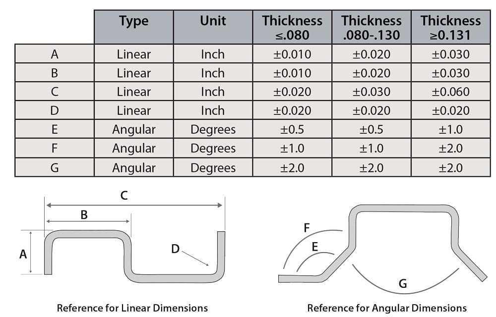
Figure 1
This tolerance guide shows reasonable tolerances for real-world bending applications. Note that “D” references the inside radius.
How severe the angular variation is depends on the die opening. The smaller the die opening is relative to the material thickness, the greater the angular variation. Why, exactly? It goes back to the basics of air bending. When air bending, the die angle does not establish the bend angle. The main reason different die angles exist in air bending is not to bend different angles, but instead to allow the punch to descend far enough into the die space to overbend for springback.
What determines an air-bent bend angle is the relationship between the width of the die opening and the depth of penetration into the die space. Depth of penetration is determined by the position of the punch tip at the bottom of its stroke—which can be extraordinarily repeatable these days—and the material thickness—which, alas, is not as consistent.
Having a precise depth of penetration becomes even more critical when using narrow die openings. Change the depth of penetration in a wide die, and the bend angle will change just a little; change the depth of penetration a miniscule amount with a narrow die, and the bend angle changes significantly. This is why material thickness variation affects the bend angle, especially for narrower dies.
“A mere plus or minus 0.006 in. variation in material thickness can represent as much as 4 degrees of angular variation,” Benson said, “and maybe more. And the variation can be even greater if you’re alternating material grain directions from part to part,” bending perpendicular to the grain (across) for one part, then parallel with the grain on the next part.
The problems don’t stop with angular variation. Material thickness variation changes how the material elongates during bending.
This in turn changes what the original blank dimensions need to be. Consider that 10-ga. A36 material. On the lower end of the gauge range, at 0.129 in., the bend deduction equals 0.221 in.; at the upper end of 0.141 in. thick, the bend deduction is 0.237 in.
“That means that the bend deduction can fluctuate as much as 0.016 in. from part to part,” Benson said.
This makes it just about impossible for many press brake operators to hold a tolerance of 0.005 in., especially on parts with multiple bends that compound the errors. A tiny error on the first bend can become a very large error by the last bend.
This isn’t to say that such precision bending doesn’t take place, as long as a fabricator has the proper controls, especially of its raw material. Quality material will help any press brake operator, whether they’re working on an old press brake or one of today’s advanced bending systems.
Precision fabrication is all about touting capabilities that come with having the latest equipment and the best talent and processes. Say a shop can tout its bending department’s capability of holding ±0.0050-in. dimensional tolerances on a formed part. That’s a competitive advantage, right?
In some cases, yes, but only if holding such a tolerance has value in the end product. But what if it has no value? What if a fabricator doesn’t really need to hold ±0.005 in.? What would happen if those tolerances were loosened to ±0.010 in., or even 0.020 in.? And what if those angular tolerances were expanded from just a half a degree to 1 or 2 degrees?
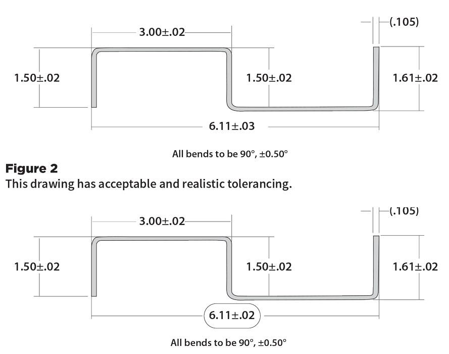
Figure 2
This drawing has an unreasonably tight tolerance of the overall dimension of 6.110 in.
“Having a handy guide to compare your called tolerances will profoundly affect your production,” Benson explained.
By a “handy guide,” Benson means a guideline specifying reasonable tolerances for a formed part, both for linear and angular dimensions, as shown in Figure 1. “You will no longer be making unreasonable demands, and no longer will you have any unrealistic expectations.”
As shown, a single feature or dimension can be very precise; but perform measurements that incorporate features in between, be they angular or dimensional, and the “reasonable” tolerance loosens. Thicker material also will have greater dimensional and angular variations from part to part.
As the number of bends increases, the acceptable variation, both angular and dimensional, should increase as well. Bending technicians know this; they often just take it for granted, but why is this? It goes back to material property variation.
Consider the dimensional variance. The “edge to the outside surface of the bend” dimension must deal with only one set of material thickness variations—that is, the variation created when bending different thicknesses, each with different elongation characteristics during bending. If the technician has another bend to make in the part, he must deal with another set of variables that builds off the first set. Thanks to material thickness variation, the first bend elongated the material by a different amount, which makes the second bend dimensionally inaccurate even before the punch tip contacts the sheet.
By no means do bending tolerances need to be extraordinarily loose either. As Benson and Boden described, a lot of effort in this business goes into correcting what would seem to be minute details. In bending, small changes can make all the difference.
Boden referred to Figures 2 and 3. The two are nearly identical drawings, including the same dimensions and 0.105-in. material thickness—except for one critical detail. The 6.110-in. overall dimension in Figure 2 is specified to be within ±0.030 in., while Figure 3 is specified to be within ±0.020 in. Figure 2 represents acceptable, realistic tolerancing while Figure 3 does not.
That seemingly small change in the tolerance makes all the difference. This is because that overall dimension must incorporate three sets of variables. As Benson explained, “These would be the possible errors over the three flange dimensions, and four bends, involved in attaining the 6.110-in. dimension.”
Both Benson and Boden emphasized that a precision bending operation can achieve some very tight tolerances, but it takes time, money, and effort to achieve them. Achieving such precision can be a worthy endeavor, but only if such tight tolerancing is necessary for the product to function as intended.
Otherwise, why not “engineer out” the problem and design parts around realistic, achievable tolerances? Having the right design guidelines for bending can make a world of difference. As Boden concluded, “When you apply such guidelines to your drawings, your scrap rate will decrease, and it follows that your production rates will increase.”
Images courtesy of Mate Precision Tooling, www.mate.com.
ASMA LLC, www.theartofpressbrake.com


The Fabricator is North America's leading magazine for the metal forming and fabricating industry. The magazine delivers the news, technical articles, and case histories that enable fabricators to do their jobs more efficiently. The Fabricator has served the industry since 1970.
start your free subscription
Easily access valuable industry resources now with full access to the digital edition of The Fabricator.

Easily access valuable industry resources now with full access to the digital edition of The Welder.

Easily access valuable industry resources now with full access to the digital edition of The Tube and Pipe Journal.

Easily access valuable industry resources now with full access to the digital edition of The Fabricator en Español.
In this episode of The Fabricator Podcast, Caleb Chamberlain, co-founder and CEO of OSH Cut, discusses his company’s...


