


The art of gauging on the press brake
How the wrong gauging strategy can lead to cumulative error in bending
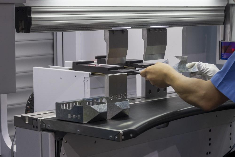
Phuchit / iStock / Getty Images Plus
Q: My company builds large power control field units for the oil industry. We had been outsourcing much of the fabrication work, but a while back we decided to bring more manufacturing in-house, including sheet metal bending. Although we’ve done machining in-house for years, we had never done any sheet metal manufacturing before. Much of it is straightforward, except for bending. No one in our shop had done any actual bending on a press brake before. We have worked through many of the forming issues on our own, except for one involving panels.
Each product we produce uses between 10 and 24 panels, and we’re having trouble assembling them. Even though we form them within tolerances specified in the print, they do not match up when we get to the last panel. Ultimately, we have to manufacture a single custom panel to make it all fit correctly. Why does this happen consistently, and what can we do to correct it?
A: I get similar questions from time to time about cumulative error when placing multiple “like” parts together to build a completed unit. The solution can be a bit tricky. It is all in how you are gauging the parts.
Errors and Gauging
Some minor errors can be attributed to the press brake, but not many. Most errors come from the sheet metal itself, though they’re not really “errors” so much as they are variations within the material aspects and their related tolerances. For example, sheet metal has a tolerance zone for thickness. In 16-ga. sheet, that tolerance runs from 0.053 to 0.067 in. Material has tolerance zones around hardness, yield strength, ultimate tensile strength, and more. The material is considered “good” if its characteristics remain within the tolerance limits.
Nonetheless, all of those minor variations within the tolerance zone can affect forming dramatically. For example, a change in thickness changes the final formed dimension. It also changes the bend deduction and the bend angle. Each of the variations adds up to a lot of differences from part to part. Some forming problems can come from machine errors, but again, these are minor.
Calculating Cumulative Error
You’re probably forming something similar to the panel in Figure 1. Let’s say your overall panel dimension is consistently off by 0.015 in. It’s within your overall tolerance of ±0.020 in., but by the time you multiply 0.015 in. by 20 panels, how much cumulative error do you have? That’s right—you have a total of 0.300 in. of error when the unit is assembled. No wonder you need to build a single custom panel to complete the project, wasting resources, time, and talent.
If we gauge from the cut edge to the first bend, we hold that dimension; that is, we maintain the dimension between the edge and first bend and push the error inward. Now, what happens if you gauge off the first flange to make the second bend? You’ll hold the dimension between the first and second bend. So, where does the error end up? It goes to the overall dimension. Add up that error from panel to panel, and you’ll find the assembly won’t fit and you’ll need to make that final custom panel.
Generally speaking, you need to gauge the first bend from the cut edge to hold that dimension—especially if there are called dimensions between features on opposing flanges, as shown in Figure 1.
Our error must go between flange one and two, and we need to hold the overall dimension. But how do we do this? The answer is all about where you gauge the part.
Again, whenever you gauge from a cut edge to the first bend, all the error moves inward, and you hold the dimension from the edge to the first bend. Next, the stops move, and you make the second bend off the first bend, holding the dimension from flange to flange, between the first and second bends—but the error hasn’t vanished. Big or small, any error moves inward and becomes part of the overall dimension. In this case, when you have 10 to 20 panels stacked side by side, the overall dimension is the last place you want the error to appear!
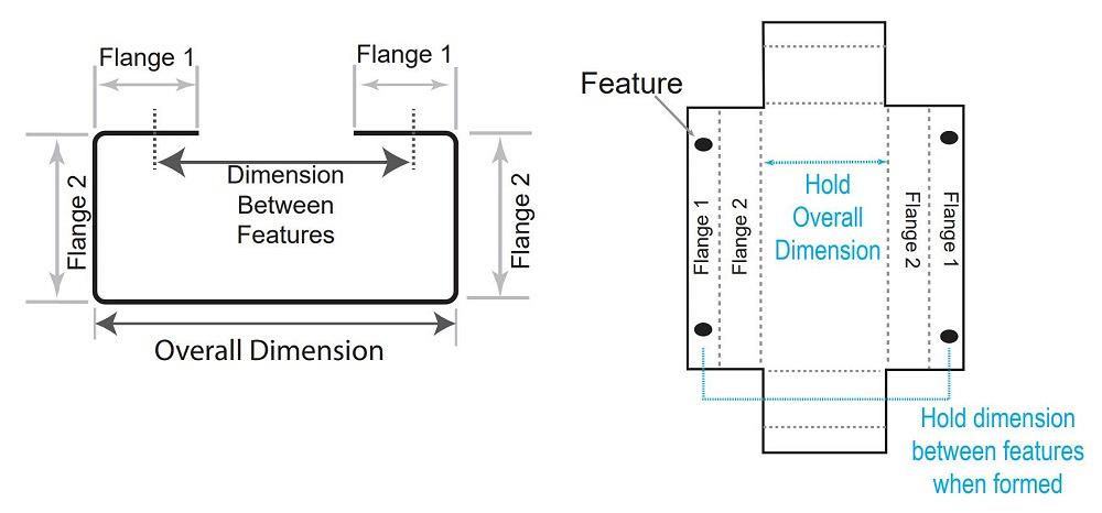
FIGURE 1. To avoid cumulative error and ensure a smooth assembly operation, you need to hold the overall dimension as well as the dimension between the features.
Place the Error Right Where You Want It
Each bend might be well within the specified dimensional tolerance, but some error will still be there, and you need to put it where it won’t cause cumulative error over multiple parts or panels. Again, if you gauge from a cut edge and then gauge the second bend off the first bend, you’re moving the error toward the center and the overall dimension, which is precisely what you do not want to do.
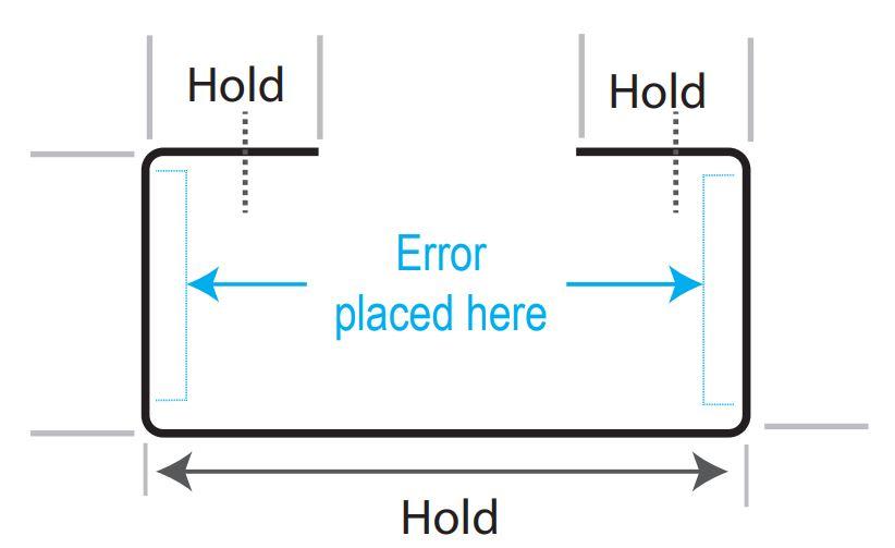
If you need to hold the first flange dimensions because you need to hold the dimensions between features on opposing flanges, you need to gauge directly from the cut edge. You also will need to hold the overall dimension. To accomplish this, the error must go on the second flange (see Figure 2). To do this, you can’t create the second bend by gauging off your first bend. Again, that will cause you to hold the dimension of the second flange and push the error inward into your overall dimension. Instead, you’ll need to gauge off the notched edge.
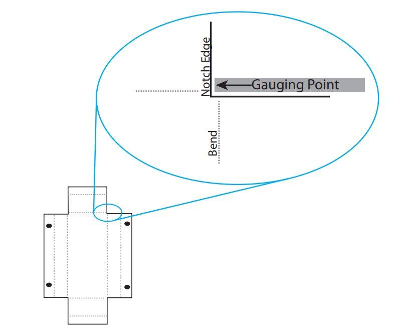
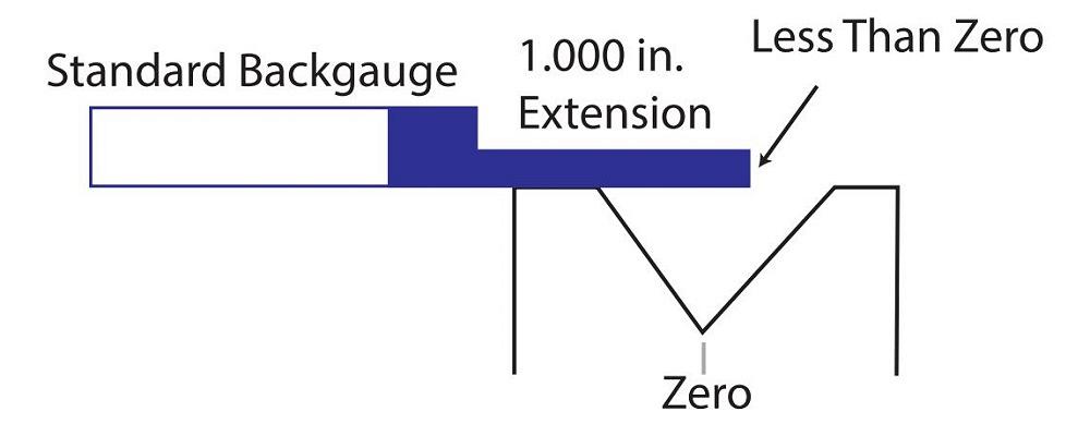
To do this, you most likely will need to gauge at a less-than-zero location, past the bend line. That’s because the notch that gives clearance for your perpendicular flanges probably has an edge that’s slightly ahead of the bend line you need to make (see Figure 3).
To accommodate this, you’ll need custom backstops, allowing the controller to have a positive dimension while still allowing you to locate the workpiece past the bend line. You can build your custom backgauge stops as shown in Figure 4 or something similar, specific to your particular make and model of press brake.
Programming Tips
Write your program for the first set of bends 1.000 in. longer than the edge-to-bend line dimension. Do not re-origin your backgauge to accommodate the new, longer stops, or you will never get the backgauges to a negative position (past the bend line) on the second set of bends.
In the controller’s mind, a dimension that gauges the notch at less than the bend line will program at slightly less than 1.000 in. Make sure that the stops are not underneath the punch when in location.
Next, program in a retract; at the pinch point, pause the program long enough to allow the backgauges to move out of the way before completing the bend. Once you get the program tuned in, you will be able to produce a final part that holds the overall dimension while simultaneously holding feature dimensions across the backside.
Gauging Alternatives
You can use other gauging techniques to place the error right where you want it to be. If you are familiar with pin gauging, you know it’s old-school for sure, but it’s still valid even on today’s press brakes (a subject I’ll be covering in a future column).
Give some thought to the technique used to solve the issue that we just reviewed, and you will find that there are many ways to apply gauging from notches or features to improve products. In any part, simply moving the inherent errors around allows you to achieve the desired results rather than constantly pushing the error toward the center, requiring you to build that last custom piece to complete the final assembly.
About the Author

About the Publication

subscribe now

The Fabricator is North America's leading magazine for the metal forming and fabricating industry. The magazine delivers the news, technical articles, and case histories that enable fabricators to do their jobs more efficiently. The Fabricator has served the industry since 1970.
start your free subscription- Stay connected from anywhere

Easily access valuable industry resources now with full access to the digital edition of The Fabricator.

Easily access valuable industry resources now with full access to the digital edition of The Welder.

Easily access valuable industry resources now with full access to the digital edition of The Tube and Pipe Journal.

Easily access valuable industry resources now with full access to the digital edition of The Fabricator en Español.
- Podcasting

In this episode of The Fabricator Podcast, Caleb Chamberlain, co-founder and CEO of OSH Cut, discusses his company’s...
- Trending Articles
1
How to set a press brake backgauge manually

2
Capturing, recording equipment inspection data for FMEA

3
Tips for creating sheet metal tubes with perforations

4
Are two heads better than one in fiber laser cutting?

5
Hypertherm Associates implements Rapyuta Robotics AMRs in warehouse
