


Regional Sales Manager
When fabricators think bending, they most likely think of a press brake. It’s as common a sight in a job shop as the spark from a welder’s torch.
But a press brake isn’t the only way to tackle a bending job—nor is it often the best way. Panel benders can do the job as well, handling materials from 0.020-inch to 0.125-in. steel. Even for one-offs or very limited runs never to be repeated, a panel bender should be considered as another tool in a fabricator’s forming arsenal.
The panel bender does not rely on the operator’s skill to reference or bend the part. A machine operator simply loads the blank. Referencing, part manipulation, and bending are completely controlled by the machine and its software.
As a blank is being loaded, the panel bender automatically adjusts to the correct tooling length in a matter of seconds.
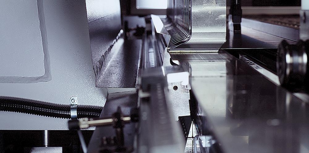
A panel bender doesn’t look like a press brake, and it doesn’t perform like one either.
Instead of relying on a ram to force the sheet metal blank into a die opening, the panel bender forms parts by holding the blank in place while a pair of bending blades contact the material to make upward or downward bends. The blades do not move in a straight up-and-down line, but rather oscillate around a single bend point until the desired angle is achieved.
It’s one thing for a fabricator to have a mental image of how a machine tool such as a panel bender might work, but it’s another thing for that same fabricator to understand what parts are a good fit for that type of bending technology. To assist in evaluating and selecting the best option, let’s take a look at five parts and see why they may or may not be a good fit for a panel bender.
This 16-gauge, NEMA-style box (see Figure 1) is a familiar sight to many fabricators. It’s a bend-intensive part that relies on correct bends so that the box fits up tightly before it’s sent to welding.
This typical box requires four bends on each side along with weld tabs on the top that wrap around the sides. Opposing weld tabs are attached to the sides and wrap around the bottom.
The forming process takes approximately 108 seconds on a panel bender—about 5.4 sec. per bend.
If this piece were to be done on a press brake, it would be very operator-intensive, with plenty of part manipulation required to accommodate the number of bends. A seasoned press brake operator might be able to push this box through the bending sequence at a pace of about 8 sec. per bend.
The other part attribute that makes this electrical box a suitable job for a panel bender is the first down bend. The part design calls for a small bend of 0.18 in., which is only 3 times the material thickness.
These bends are very hard to do on a press brake. In fact, most shops require special tooling to accomplish a bend this tight. That’s not the case for a panel bender.
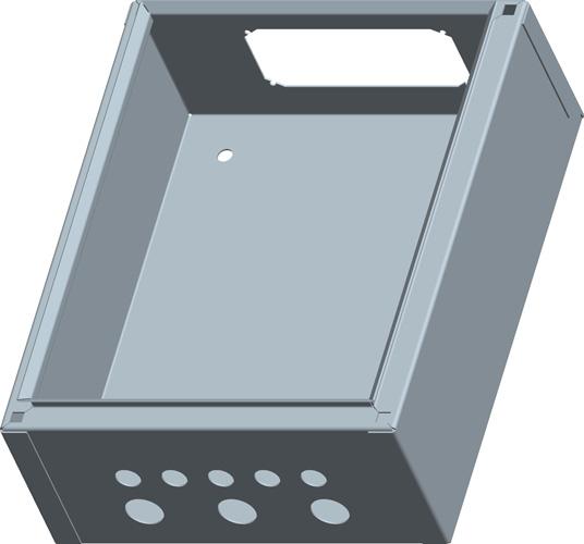
Figure 1
A panel bender can move tooling into place quickly to accommodate the forming of this 18-bend electrical box. As the bent forms are created, blank-holding tooling is moved automatically to eliminate any potential interference with the previously bent flanges.
The other factor to consider is that by starting with such a short flange on a press brake, the operator has to be absolutely focused on properly backgauging the part. Because all subsequent bends are measured off of that original bend, the first bend has to be correct. On a panel bender, the part is referenced only once.
The bend position is calculated from the center of the blank to each bend, resulting in a ±0.004-in. bend to bend accuracy with no tolerance stack. A manipulator moves the blank per the instructions from the control software, ensuring the part is where it needs to be—from the start of the job until the finish.
Every box needs a lid. This lid (see Figure 2) is 16 gauge as well and takes about 40 sec. to complete at a 5-sec.-per-bend pace on a panel bender.
This part requires eight bends, which is not difficult to do on a press brake. The difficulty arises with the short hem that requires a special hem die if done on a press brake. Unless a brake is dedicated to forming hems, the operator is likely going to have to stop the bending process, find the special tooling, and manually make the changeover.
Panel benders are able to form angles from 0.1 degrees to 180 degrees with universal tooling.
Thus, the forming of a hem never requires a stop in production.
The ability to process hems quickly and without an interruption in production flow might open the door to incorporating more hems into the product design. Adding four hems to a part increases the cycle time by about 6 sec. In some circumstances, adding a hem for increased rigidity might be a welcome suggestion.
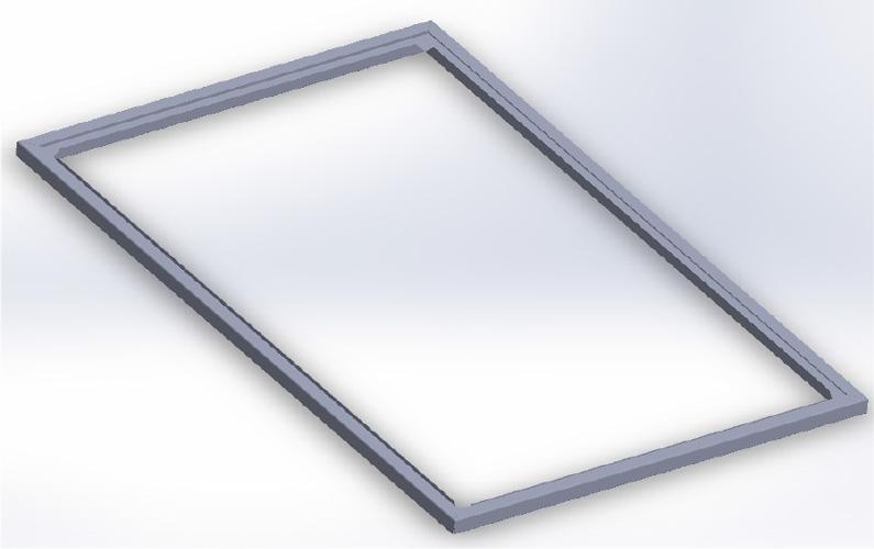
Panel benders can’t handle everything, and this frame is one example of that (see Figure 3). It is made of 20-gauge steel and contains eight perimeter bends and four internal bends.
The owner of a panel bender might choose to make the first eight perimeter bends on the panel bender, but is that really the best sequence decision? The part would need to have the internal window attached with tabs to allow the panel bender to hold and manipulate the part. Often the clamping device would be able to hold the part off-center and jump over a window or large hole, but the clamp still needs 1 in. of material to do this.
Additionally, the internal bends are facing toward the center of the panel, which the bending blades are not able to reach. The remaining four bends have to be moved to the press brake to complete the part. The additional operation and material handling do not make for a lean manufacturing process for this particular part. The perimeter bends might be faster on a panel bender, but that advantage is wiped out with the need to move to a secondary operation.
Fabricators walking the floor of FABTECH® typically see large panels being run on the panel benders. That might create the perception that only large parts are a fit for panel benders. That’s simply not the case.
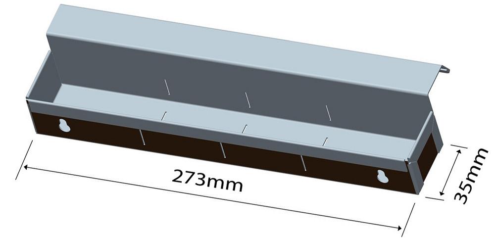
This tray (see Figure 4) is a good example of a small part that makes sense for a panel bender. The 10.75- by 1.40-in., 20-gauge part takes 96 sec., or 4.5 sec. per bend, to fabricate.
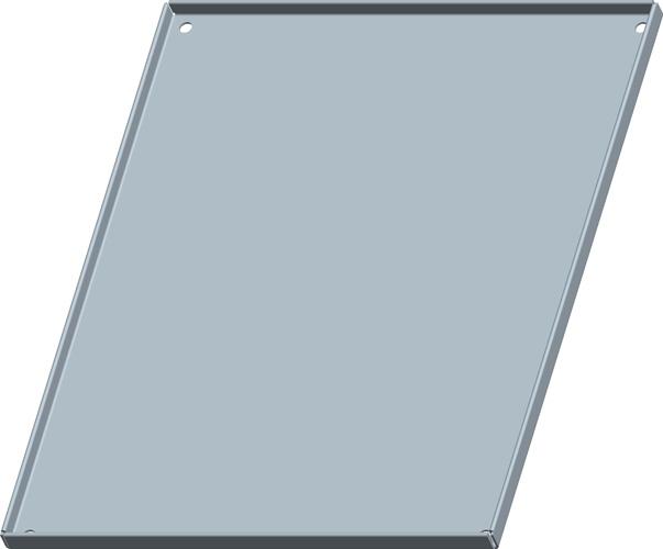
Figure 2
An electrical box lid such as this is more suitable for a panel bender than a press brake because of the hems.
Again, the hem along the length of the part makes this stand out as a definite candidate for the panel bender. The hem might actually prove to be a design improvement because the addition of hems adds both a safety feature and strengthens the part, allowing for the use of a thinner-gauge material. Even made of 18-gauge steel, the part would still be rigid. For such a small part, a little weight removal might not seem like a big deal, but if dozens of those trays were to be used in the back of a utility truck, the combined weight savings might contribute to fuel savings or the ability to carry more equipment.
These parts could be formed on a press brake, but small parts on older hydraulic press brakes can be challenging. Fabricators call these types of parts “finger pinchers” for a reason.
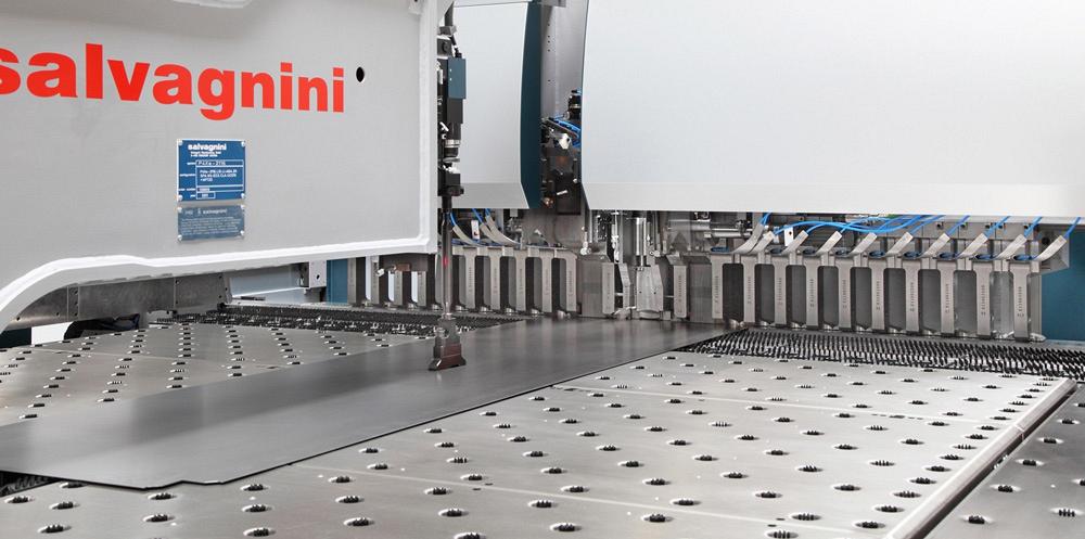
This 72- by 48-in., 12-gauge panel takes about 36 sec., or 4.5 sec. per bend, to fabricate. The number and size of the bends are not what make this large panel suitable for a panel bender—it’s the overall size of the part.
If this part were to be bent on a press brake, it would require two operators to maneuver and support it. Two individuals lifting a panel of this size might knock out the first couple of parts pretty quickly, but as the shift goes on, they will probably experience some fatigue, slowing down and producing fewer than an optimal number of parts per shift. Rarely do process time studies take into account manual labor slowing down over a full day or shift in front of a machine.
The panel bender can position a large panel quickly and precisely for all of the bends. The entire job takes fewer than 40 sec. per panel over the duration of the shift, as long as the operator is keeping up with material loading and unloading!
These different parts are just a few examples of why a fabricator should investigate panel bending as a possible alternative to forming with a press brake. It should be noted that process flow could play a role as well when it comes to considering a panel bender for the shop floor (see Figure 6).
Plenty of fabricators talk about creating kit assemblies for regularly occurring products, but that is rarely achieved in an efficient manner. Because fabricators want to maximize setup time on a limited number of press brakes, they might run 50 or 100 pieces of one part, change over the tooling to run the required number of parts for the rest of the kit, and then sort the kits downstream right before assembly.
A panel bender allows a fabricator to kit in a just-in-time manner. An operator can run all parts of a cabinet—left side, right side, top, bottom, and back—in sequence on a panel bender and send that downstream as one kit. The fabricator doesn’t have to focus on 50 tops, 50 bottoms, and so on, to mitigate the press brake setup time.
In the end, fabricators must do their homework to decide if panel bending is a good fit.
As these machines are so inherently different than press brakes, the equipment manufacturers themselves are the best source of knowledge. Take advantage of this and send in files for analysis; you may be surprised at the panel bender’s capabilities.

The Fabricator is North America's leading magazine for the metal forming and fabricating industry. The magazine delivers the news, technical articles, and case histories that enable fabricators to do their jobs more efficiently. The Fabricator has served the industry since 1970.
start your free subscription
Easily access valuable industry resources now with full access to the digital edition of The Fabricator.

Easily access valuable industry resources now with full access to the digital edition of The Welder.

Easily access valuable industry resources now with full access to the digital edition of The Tube and Pipe Journal.

Easily access valuable industry resources now with full access to the digital edition of The Fabricator en Español.
In this episode of The Fabricator Podcast, Caleb Chamberlain, co-founder and CEO of OSH Cut, discusses his company’s...


