


Think press brake work is simple? Think again
If press brake operators know the basics, they know sheet metal bending isn’t easy
The press brake ram descends, the metal bends, the cycle repeats. It looks pretty straightforward to the uninitiated. But it’s not that simple. Not by a long shot. Getty Images
To the uninitiated, bending sheet metal on a press brake looks simple. You put a punch and die set into the press brake and the ram makes the punch move down into the die space to bend the sheet metal. It’s so simple, anybody could run this machine, right?
Not so fast. While the machine appears to be simple, it turns out that press brakes are one of the most challenging machines to master. Consider Figure 1, which illustrates just some of the variables press brake operators work with every day.
This error in perception is often held by human resource people, mid- and top-level managers, and other leaders. Their perception and resulting lack of support often takes the profit right out of a project. Business leaders who fail to grasp the press brake’s complexity tend to hire the wrong people.
Operating a press brake is not for everyone. Some who want to run one should not be anywhere near a press brake. Others would make great technicians but want nothing to do with the press brake. And then there are those rare individuals who want to learn the craft. They want to learn the hows and whys, and they seem to “just get it.” Good luck finding one of these people; they are hard to come by.
The same thing applies to engineering and the general lack of knowledge about designing for press brake forming. Inadequate knowledge about metal forming has led to many harmful practices as operators try to correct problems on the shop floor using knowledge passed on tribally. Such training is not a good thing, especially because the teaching of tribal knowledge often suffers from “replicate fade.” Every time you pass on knowledge, your student retains only 80% of it.
Just one critical error can lead to failure. Therefore, it is essential that you completely grasp the metal forming process, bending techniques, and the nuances of forming on a press brake.
Accounting for Elongation
Bending sheet metal elongates the workpiece at the point of the bend. During the bending process, the outside surface of the bend is subject to expansion or tensile stress, while the inside surface is exposed to compressive stress. At the border between expansion and compression is a theoretical area that goes through no physical change during forming. This neutral axis is not affected by tensile or compressive forces and so has no expansion or compression.
During bending, the neutral axis moves from 50% in the flat (that is, the middle of the material thickness) toward the inside bend radius, somewhere between 0.5 and 0.273 (the result of the t/Mt calculation in Figure 1). We use a k-factor to calculate the location of the relocated neutral axis. Some applications use an average k-factor (0.446 is common), some refer to charts, and some rely on test pieces. For more information on the k-factor, check out “Analyzing the k-factor in sheet metal bending,” a two-part series.
To account for this elongation, the industry relies on three common methods: the bend allowance method, the empirical method (often used in plate applications), and the bend deduction method.
Bend Allowance Method. This is best suited for calculating bend angles other than perpendicular, though it works for 90-degree bends as well. We define the bend allowance (BA) as the length of the neutral axis between the tangent point, as shown in Figure 1.
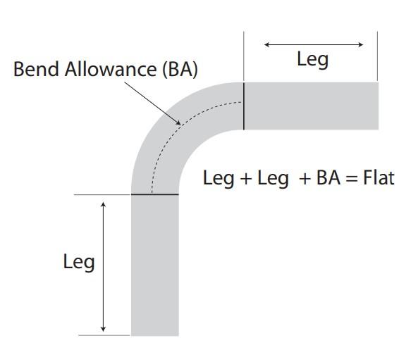
Because the neutral axis measures the same length before and after forming, we can use it to calculate the flat size of a part. First, determine the two flange dimensions from the edge to the tangent point of the radius and flat. Next, add that result to the neutral axis’s length (the BA), and you’ll get your total flat blank size (see Figure 2).
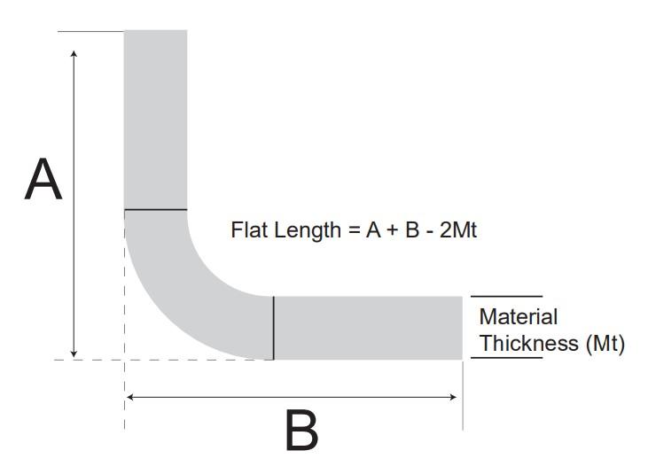
Empirical Method. This method also works well for 90-degree bends and other bend angles, and it can assist designers when calculating the elongation of the part. To calculate the flat blank using this method, as shown in Figure 3, you simply add the leg dimensions to the apex (the apex of the bend is illustrated in Figure 1), then subtract twice the material thickness (Mt): Leg A to Apex + Leg B to Apex - 2Mt = Flat length.
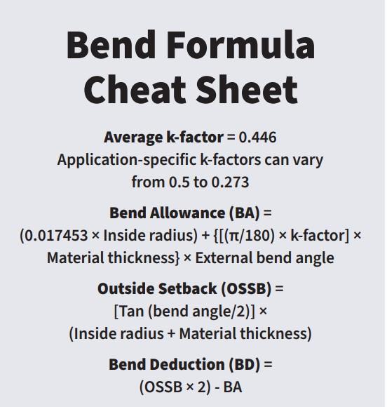
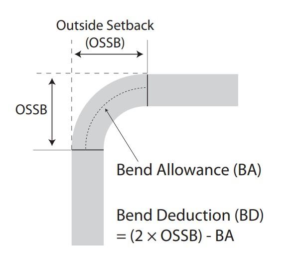
Bend Deduction Method. This method incorporates the bend deduction (BD). You calculate the BD by doubling the outside setback (OSSB) and subtracting the BA (see Figure 4). From here, you subtract the BD from the outside dimensions: (Dimension to apex + Dimension to apex) - BD. For a review of all the formulas, check out the Bend Formulas Cheat Sheet figure.
For more on all of this, check out “The basics of applying bend functions," as well as the “A grand unifying theory of bending on a press brake,” a four-part series that ran in 2015.
Selecting an Appropriate Toolset
How to select the right tools for bending has always been an issue. The toolset consists of an upper and lower tool. The upper tool is called the punch and the bottom tool is called a die.
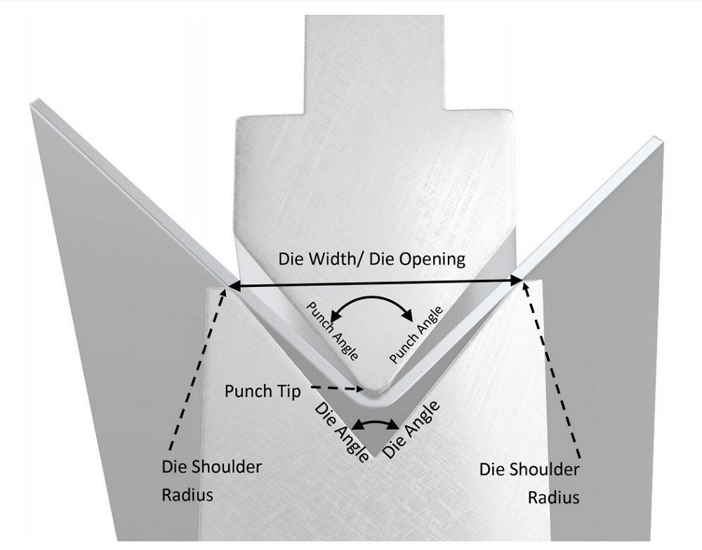
Technicians choose punches and dies to account for the material thickness, the bending radius, and the method of forming (air bending, bottom bending, or coining). The punch angle must be equal to or less than the die angle (see Figure 5). The tool angle combination should help you compensate for springback, which is the material’s tendency to relax a degree or two when released from the pressure applied to create the bend. The die opening must be of a size appropriate for the desired inside bend radius.
Selecting a Die. If you select a die opening that is too small, you will damage the part and possibly raise the tonnage to dangerous levels. Select too large of a die opening, and you create a larger radius than planned, which changes the bend’s elongation value while taking your part out of tolerance. All this applies regardless of the forming method or tool style.
The industry uses various die profiles. The most common is the V die followed by the channel die. There’s a lot to selecting a die width regardless of the die profile. If the inside bend radius is equal to the material thickness, the rule of thumb is to use a die opening equal to eight times the material thickness. Sometimes, though, the die opening should be 10 to 12 times the material thickness, especially for thicker materials. But there’s more to it than that. For more detail, check out “Predicting the inside radius when bending on a press brake.”
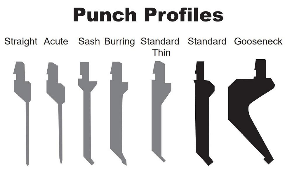
Selecting a Punch. Custom tools aside, press brake punches come in two general styles, the straight punch and the gooseneck, with almost every other punch profile being a variation of one of the two (see Figure 6).
If the nose radius on the punch is too small, it will penetrate the material’s surface, causing a crease in the center of the bend. This crease is a sharp bend and will amplify any angle variations caused by variables within the material, the material thickness, hardness, and, in some materials, even the grain direction.
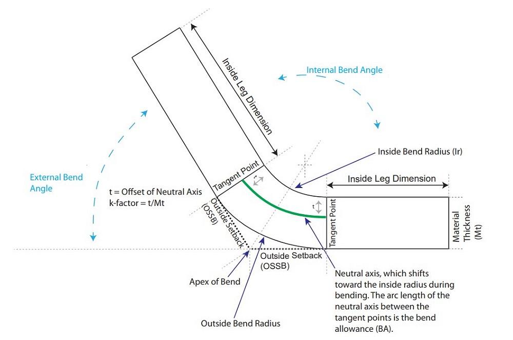
FIGURE 1. If you think bending metal on a press brake is simple, think again. This illustrates just some of the variables press brake operators work with every day.
Tonnage Considerations
Forming tonnage is another issue that both the operator and the part designer need to be aware of. Become familiar with forming tonnage charts. Learn how to read and apply them, and be sure to adjust the values for various types of metal. A typical forming tonnage chart might apply only to 60,000-PSI-tensile-strength mild cold-rolled steel.
If you overlook this step, you could damage the part, the punch, the die, the press brake, or all of the above. You could also put your operator in a dangerous situation.
Select toolsets according to the part’s required inside bend radius—unless the total tonnage required for the bend will exceed the tool’s tonnage rating, which is something that you never want to do. For much more on tonnage, check out “The 4 pillars of press brake tonnage limits.”
Minimum Flange Size
Expanding on last month’s column about minimum flange sizes, this month we’ll look at the minimum flange that can be produced on a given die opening. To determine that minimum flange value, you need to take the radii on the top two edges of the die (that is, the die radius) into account.
When the flange is short and close to the die radius, the part can slip enough to taper the flange or just snap straight into the die space. Calculating the minimum flange before the parts make it to the floor will save a lot of time, aggravation, and scrapped parts.
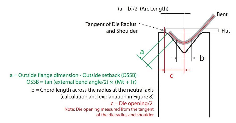
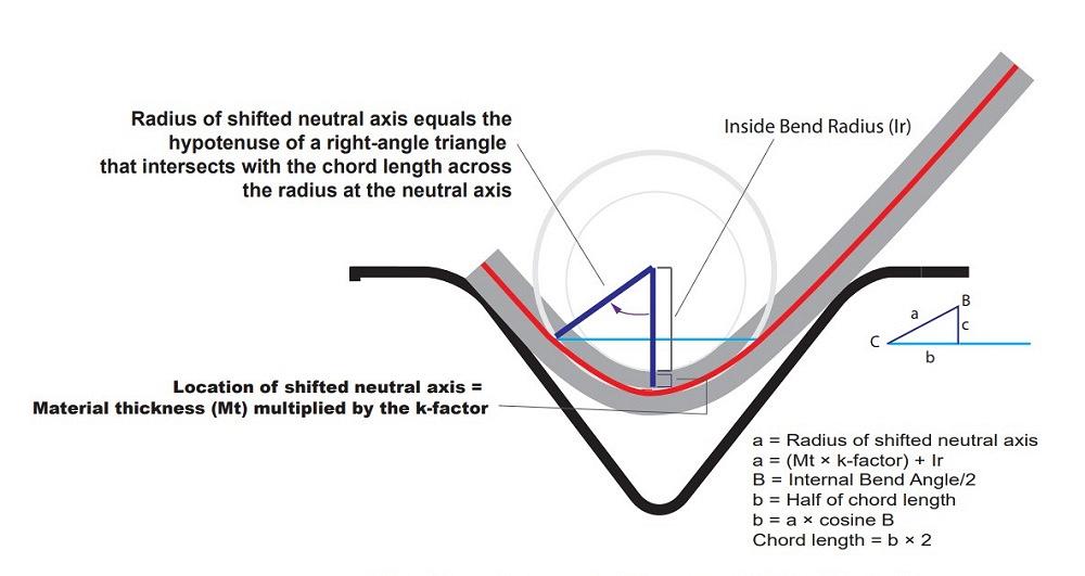
To do this, consider the variables in Figure 7. You need to calculate the flat length between the edge and the tangent point, where the flat leg transitions to the radius (a). You also need to know the chord length across the radius at the neutral axis (b), and the dimension from the center of the die to the tangent point of the die radius and the die shoulder’s flat (c). To determine these values, you can use the calculations described in Figures 7 and 8.
Once you determine values for a, b, and c, you can calculate the minimum flange dimension that can be bent over the die. If (a + b)/2>c, then the flange can be bent. If (a + b)/2≤ c, the flange cannot be bent and the part will slip into the die space.
Tip of the Iceberg
These are just a few of the many considerations involved in producing parts on a press brake. You can see that bending is not as simple an operation as it might seem to be at first glance.
In fact, bending metal on a press brake turns out to be one of the most challenging operations in a sheet metal shop. It takes a lot of knowledge, experience, and planning to make it all come together. And this is just a start. We haven’t even considered how the press brake itself affects the forming process.
Precision Press Brake Certificate
This two-day intensive seminar Aug. 8-9 with instructor Steve Benson will teach you the theory and math fundamentals behind the machine to uncover the secrets to working with press brakes. You’ll understand the principles behind quality sheet metal bending through interactive instruction and sample work problems throughout the course. With easy-to-understand exercises, you will learn the skills needed to calculate accurate bend deductions, select the best tooling for the job, and determine the correct v-die opening to avoid part distortion. Visit the event page to learn more.
About the Author

About the Publication

subscribe now

The Fabricator is North America's leading magazine for the metal forming and fabricating industry. The magazine delivers the news, technical articles, and case histories that enable fabricators to do their jobs more efficiently. The Fabricator has served the industry since 1970.
start your free subscription- Stay connected from anywhere

Easily access valuable industry resources now with full access to the digital edition of The Fabricator.

Easily access valuable industry resources now with full access to the digital edition of The Welder.

Easily access valuable industry resources now with full access to the digital edition of The Tube and Pipe Journal.

Easily access valuable industry resources now with full access to the digital edition of The Fabricator en Español.
- Podcasting

In this episode of The Fabricator Podcast, Caleb Chamberlain, co-founder and CEO of OSH Cut, discusses his company’s...
- Trending Articles
1
Capturing, recording equipment inspection data for FMEA

2
Tips for creating sheet metal tubes with perforations

3
Are two heads better than one in fiber laser cutting?

4
Supporting the metal fabricating industry through FMA

5
Hypertherm Associates implements Rapyuta Robotics AMRs in warehouse
