


When there is no choice but to bend sharp on the press brake
Be prepared for an unstable, unpredictable metal forming operation
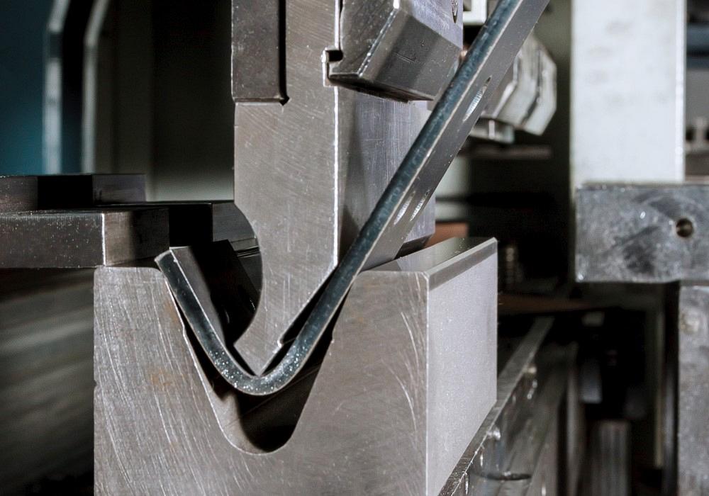
If press brake operators bend sharp, they should be prepared for metal parts with greater variations from bend to bend and flange to flange. Getty Images
I have in front of me two completely different questions that have the same answer. Take a look at them and have a go at answering them yourself. Think about what they might have in common and what possible solutions could work for both.
Question 1: Is there a formula for back-figuring a bend deduction from the bottom die? Sometimes our press brake person will use a smaller V opening that we have not figured for in our flat layout. We use the standard bend deductions.
Question 2: Is there a way to calculate a flat pattern of a part with a sharp bend? I know that sharp bending is inherently inaccurate, but I was hoping there was a way to at least calculate to some degree when a bend turns sharp. We have a limited tool selection, and we run into instances where we have no choice but to use tooling that produces a sharp bend.
Answer: First, I assume you’re both air-forming. If you were bottom bending, the part’s inside bend radius would be based on the punch nose radius. The radius would be consistent and predictable pretty much every time.
Because you’re air-forming, you could refer to bend allowance or bend deduction charts. Regardless, air forming floats (creates) the inside bend radius as a percentage of the die opening. It’s utterly different from bottom bending (see Figures 1 and 2). Understanding this difference is essential, as the inside radius of the bend is the heart of any precision sheet metal part in which a bend is made.
It’s never ideal to select extreme die openings that are too wide or narrow relative to the material thickness. Of course, you sometimes have no choice but to work at the extremes. Certain jobs might require you to work with a punch nose that’s large relative to the material thickness. Other jobs might force you to use a punch nose that’s sharp relative to the material thickness.
When exactly does a bend turn sharp? For more on this, see “How an air bend turns sharp.” There’s more to the story, and that will be the focus of another Bending Basics column coming very soon.
When you know whether the bend is sharp or not, you can determine what the inside bend radius will be. You then use that to calculate your bend allowances, outside setbacks, and bend deductions. Calculate them right, and you’ll form parts right the first time.
It Starts With the Die Opening
When you air-form, you calculate the bend allowance and bend deduction from the die opening. The inside bend radius of the part is established as a percentage of the die opening. The percentages change by material type:
- 304 stainless steel: 20% to 22%
- 5052 H32 soft aluminum: 10% to 12%
- Hot-rolled pickled-and-oiled steel: 14% to 16%
- Low-alloy, mild cold-rolled steel: 15% to 17%
Knowing this, you take the dimension of the die opening and multiply it by the appropriate percentage. The range of percentage values helps account for the numerous material variables, including thickness, tensile strength, and yield strength.
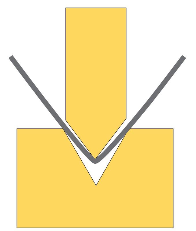
FIGURE 1. In air forming, the radius forms as a percentage of the die opening.
Most of the time, though, the median percentage works fine. For example, when working with low-alloy, mild cold-rolled steel (CRS), a die opening of 0.551 in. multiplied by the median value of 16% (0.16) should give you a 0.088-in. inside bend radius. From there, you use the empirical formulas for calculating the outside setback, bend allowance, and, of course, the bend deduction.
Again, you start with the median percentage and adjust as necessary. If you receive your material from the same supply house all the time, the material will be somewhat consistent, and you should be able to establish a standard working percentage. However, if your material comes from several different vendors, using the middle percentage value (such as 16% for CRS) will most likely yield the best results. It just takes some time, and you’ll need to pay attention to find the correct percentage.
The Outliers
What if you’re forced to use a die opening that’s too narrow or too wide, or a punch nose that’s too profound (large) or sharp (small) relative to the material thickness and die opening?
When you use a die that’s too narrow, the forming tonnage goes up and the bend radius will distort into a parabolic shape, elongating the radius. If you use a die opening that’s too large, you increase the inside bend radius. And the radius itself will no longer be a true bend radius but rather a distorted one and hard to predict. If you can’t define a true bend radius, then chances are your bend deduction, and bend allowance, will also be off.
If you’re using the correct die opening for the material thickness, how does the punch nose radius affect the results? The punch nose radius should not exceed the naturally floated inside bend radius produced by the die opening. This action would cause the material to take on the punch nose’s larger radius. This in turn would cause your bend allowance and bend deduction to be off, because the actual inside radius would be larger than the planned inside bend radius.
It is always best to get the punch nose radius as close as possible to the naturally floated bend radius without exceeding that value. With this setup, you’ll find that each bend will be more consistent, your bend angles will be stable, and your formed dimensions will require far less tweaking.
What happens when you have no choice but to bend sharp? First, let’s clarify some terminology. There are really two kinds of sharp bends. The first is the sharp bend produced in a coining operation. In coining, you are deliberately trying to create a very sharp, crisp corner in the workpiece. To accomplish this, a very sharp punch nose radius (say, 0.015 in.) descends to a position that’s less than the material thickness, effectively “stamping” the inside bend radius (see Figure 3).
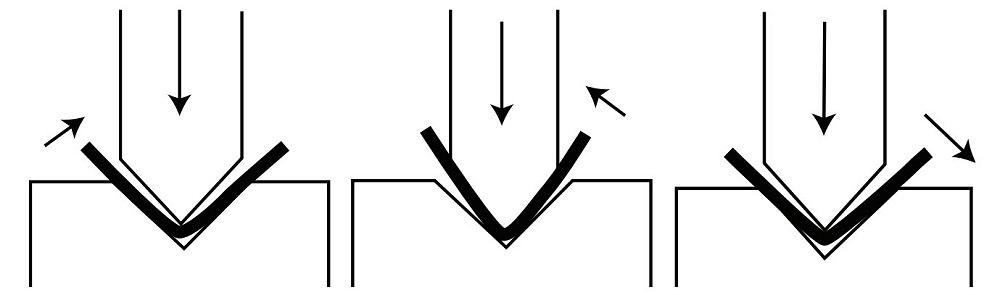
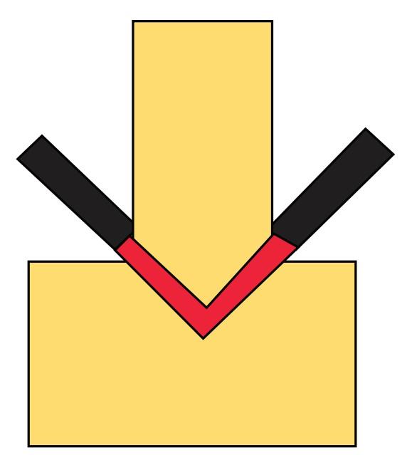
A sharp bend in an air form is different. Again, the inside radius is produced as a percentage of the die opening regardless of the punch radius, unless the punch radius exceeds the part’s naturally floated radius. Air-forming a sharp bend is an undesirable forming practice. A bend turns sharp when the job’s forming tonnage exceeds the material’s ability to resist the penetrating force from the punch nose. The punch nose land area—that is, the area that makes direct contact with the material—has so much tonnage behind it that it penetrates the surface of the material and creases the center of the bend (see Figure 4). This also distorts the inside bend radius into more of a parabolic shape, further elongating the material. When this happens, your bend allowances and bend deductions will be off.
A sharp bend relationship between the punch nose and the material amplifies any angular variations commonly seen when bending a sheet metal part. If the angle variation usually is 1 degree, a sharp bend may increase that to 2 to 3 degrees, flange to flange and part to part. And as you know, bend angle variations lead to dimensional variations, compounding the problem.
A sharp bend does not necessarily require a small nose radius on the punch. A good rule of thumb is to assume that when the inside bend radius reaches 63% of the material thickness, your bend is likely to turn sharp. This is a reasonably accurate value for mild cold-rolled steel. If you’re bending 0.25-in.-thick material, a 1/8-in.-thick punch nose radius can still create a sharp bend.
The best solution, of course, is to avoid a sharp bend relationship between the punch nose and the material thickness, at least as much as possible. Until then, check out thefabricator.com archive for more on sharp bends, and stay tuned for an upcoming column on predicting exactly when and where a bend turns sharp.
About the Author

About the Publication

subscribe now

The Fabricator is North America's leading magazine for the metal forming and fabricating industry. The magazine delivers the news, technical articles, and case histories that enable fabricators to do their jobs more efficiently. The Fabricator has served the industry since 1970.
start your free subscription- Stay connected from anywhere

Easily access valuable industry resources now with full access to the digital edition of The Fabricator.

Easily access valuable industry resources now with full access to the digital edition of The Welder.

Easily access valuable industry resources now with full access to the digital edition of The Tube and Pipe Journal.

Easily access valuable industry resources now with full access to the digital edition of The Fabricator en Español.
- Podcasting

In this episode of The Fabricator Podcast, Caleb Chamberlain, co-founder and CEO of OSH Cut, discusses his company’s...
- Trending Articles
1
How to set a press brake backgauge manually

2
Capturing, recording equipment inspection data for FMEA

3
Tips for creating sheet metal tubes with perforations

4
Are two heads better than one in fiber laser cutting?

5
Hypertherm Associates implements Rapyuta Robotics AMRs in warehouse
