


CAD/CAM Technologist

Knowing how to dimension a part in a drawing makes metal fabricating that part much easier. Drafting, which you could call the “language of industry,” is not complete without dimensioning, writes Mark Schwendau. Getty Images
One of the most important aspects of drafting parts is dimensioning. Drafting, which you could call the “language of industry,” is not complete without it.
Dimensioning can be difficult to grasp for those learning how to draft, but it’s necessary. Lack of dimensioning knowledge results in many poor and incomplete drawings in the world.
I know this firsthand because I was a professor of CAD/CAM technology for 40 years. I retired four years ago, but jumped behind the computer again when I had the chance to join a company in the steel cutting industry. My job is to prepare 2D CAD drawings in a DXF file for custom-designed parts and then program them in a nesting software for cutting machines. The nesting software, which processes the drawing as machine code, is then sent out to the shop as programs. These programs are usually TXT files containing G- and M-codes. The only time I am required to think in three dimensions is to prepare plasma bevel cutting jobs.
Now let’s explore the importance of dimensioning in part design.
During my career in technology education, I came up with my own way to teach the critical thinking process of dimensioning a part in drafting. I offered my students two little golden nuggets of knowledge:
When trying to redraw a part given to you in a drawing that is very complex or confusing, don’t worry about what you don’t know. Work the problem from what you do know. The rest will follow, and you will figure it out by breaking it down into simple geometric parts of the whole.
When drawing an existing part as a machine drawing, when you think you are done, ask yourself, “Did I provide enough information to remake this part?” Imagine you are at the kitchen table with a block of cheese or bar of soap and ask yourself if you could remake the part with a knife based on the information you just provided.
As a drafting educator, I referred to three basic types of machine parts as three different kinds of belly buttons: innies, outies, and irregulars:
The outies are parts measured from the outside in. They are generally rectangular or square and are best dimensioned from the outside working your way into the interior features. The office furniture you are sitting around now is a good example of this.
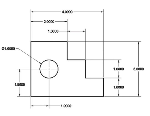
Figure 1
This is an example of chain dimensioning. It works well when tolerances are not a factor in part design.
Irregular parts are like those featuring irregular (French) curves. One could start dimensioning such objects just about anywhere. However, in general, you want to start dimensioning parts from where they are held or anchored down in the shop.
The three major types of dimensions are overall dimensions, location dimensions, and feature dimensions. A hole size is an example of the latter.
Dimensioning can be approached in five different ways: chain dimensions, baseline dimensions, ordinate dimensions, dimensions of circular parts, and tabular dimensions. Of course, combinations of several of these methods are allowable as well.
Chain dimensions are also called running or point-to-point dimensions. This is a dimensioning method whereby dimensions are broken down as parts of a whole and dimensions are connected end-to-end in a chain fashion. This is the oldest method of dimensioning.
Even though this approach has been around for years, it can lead to the problem of tolerance stackup, where individual dimensions contain a tolerance that can become cumulative. For this reason alone, chain dimensioning is the least desirable method unless the last dimension of the chain is left open and covered by an overall dimensioning adjustment. This implies that all sections of the chain are important, but the last one is less important, allowing for some tolerance to be allowable for parts to still be usable. Figure 1 offers an example.
Baseline dimensions are also called parallel dimensions or datum dimensions. They begin from one surface that is assumed to be true, flat, and perpendicular and that is thought to be an origin or starting point. These dimensions are often thought of as points of beginning or what is termed datum surfaces in machine drawing. Figure 2 shows an example.
Ordinate dimensions are also called datum dimensions, running dimensions, or arrowless dimensions. They begin from one surface that is assumed to be true and that is thought to be an origin or starting point. An ordinate dimension is often thought of as a point of beginning or what is called a datum plane in machine drawing. The term baseline comes from the ordinate or 0-X, 0-Y point being termed the X-Y origin or home. See Figure 3 for an example.
Dimensions of circular parts treat the centermark as a datum from where all dimensions begin. Only parts referencing a common centermark of concentricity can use this method. Off-center or nonconcentric parts require some modification when using this method. The practice usually requires distances be given between centers both in horizontal (X) and vertical (Y) directions. If a bolt circle is used for a circular pattern of holes about a center, the bolt circle’s diameter is given but degrees between hole centers are not given, if they are all assumed to be equal. In this example, six holes divided into 360 degrees would mean there are 60 degrees between holes.
Tabular dimensions also are referred to as tabled dimensions. In this scenario, one drawing with a table can be used to address multiple similar parts. In general, the drawing is prepared to one actual baseline part, in this case part 1001. Thereafter, all other parts would be reasonable facsimiles, but not proportionately correct to all other parts of the table.
1. Dimensions should be shown to the part’s contour that best shows a feature. For example, a hole is dimensioned where it appears as a circle.
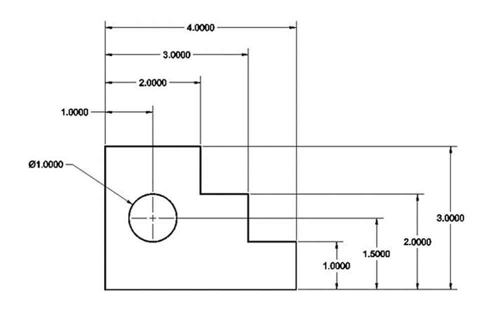
Figure 2
Some argue that baseline dimensioning is the easiest way to prepare a drawing and the easiest to read in the shop.
2. Dimensions should never be duplicated, and superfluous and redundant dimensions should be eliminated.
3. Every feature of a part, such as a hole, should be located both vertically and horizontally to its center with a dimension of size.
4. Irregular contours (like a drafting irregular curve) of a part should be dimensioned by horizontal and vertical locations to theoretical sharp corners or centers of arcs.
5. Customary English and metric dimensions should be supplied as necessary.
6. Customary English dimensions should be expressed to at least three decimal places of accuracy and metric decimal dimensions should be expressed to at least one, unless the part consists of dimensions to whole numbers.
7. As much as possible, keep dimensions off of the view of the part.
8. Always make dimension lines thinner than part object lines for differentiating dimensions from the part profile.
9. Shorter dimensions should be placed inside longer ones.
10. Dimension lines should never cross, and dimension lines should cross extension lines as little as possible.
11. Ensure all rounded corners, such as fillets and rounds, are dimensioned by both location and size either to their centers or off of theoretical sharp corners.
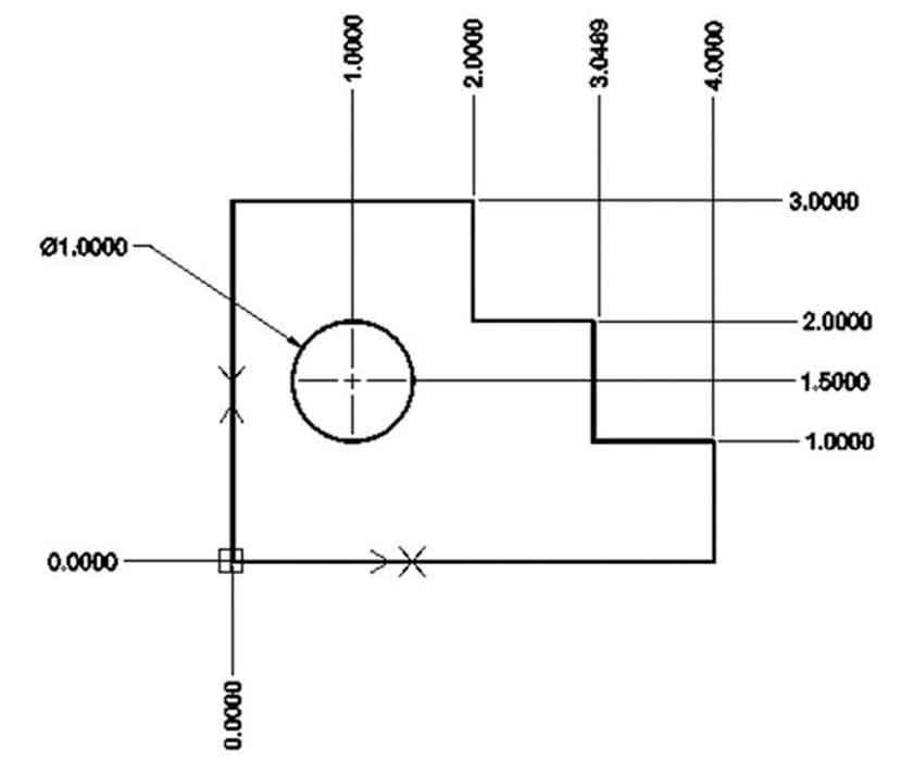
Figure 3
The term baseline actually has its origins in ordinate dimensioning. It refers to the 0-X, 0-Y point being termed home or the baseline. Here is an example of ordinate dimensioning.
12. Arcs of more than 180 degrees can be dimensioned as a diameter, while arcs less than 180 degrees should be dimensioned as radii.
13. The geometric dimensioning “times” symbol (x) should be used to summarize occurrences of diameters and radii that happen multiple times in a drawing.
14. A diameter dimension value should always be preceded by the symbol Ø. A radius dimension should always be preceded by the letter R.
15. A drawing should be dimensioned completely such that nobody needs to make calculations to determine dimensional information desired but not present in the drawing.
16. Dimension features of a part that are left, not to those features being cut away as scrap.
17. Machine drawings of mechanical parts should be dimensioned to the unidirectional method of text placement, whereby all dimensions read from the bottom of the page and are not aligned with dimension lines.
18. Fractional customary inch dimensions are used rarely in machine drawing. One example of where such units of measure are acceptable is in a foundry or forge where rough parts are the end product ready for further processing.
19. Angular dimensions should not be given to decimal accuracy unless absolutely necessary and both machine capabilities and workforce are able to hold such tolerances.
20. Drawings should not be dimensioned to any greater tolerance than what the shop can maintain, unless the part is to be jobbed out to another party. (When I was teaching in college, the drafting and design department knew that the on-campus shop could hold a dimension only up to 0.0015 in.)
Drawing information is transmitted to me where I work in three different ways. They can be classified as good, better, and best. A good drawing is a hard-copy hand sketch or a drawing with both part geometry and dimensions. A better drawing is a PDF CAD file complete with both part geometry and dimensions. The best is an electronic drawing file complete with both part geometry and dimensions.
Mark Schwendau is a retired professor of CAD/CAM technology, Kishwaukee College, Malta, Ill., and is now a CAD/CAM technologist at Accurate Metals Illinois.
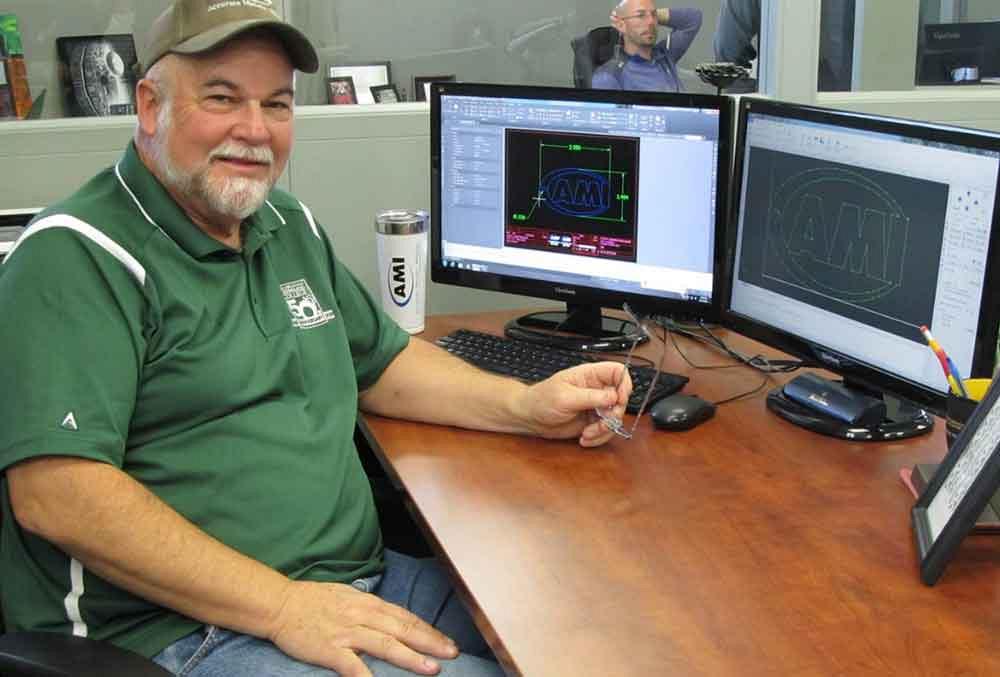
Mark Schwendau is a graduate of Northern Illinois University’s College of Engineering and Engineering Technology and taught CAD technology at Kishwaukee College, Malta, Ill., for many years. For the last three years he has been employed as a CAD/CAM technologist for Accurate Metals Illinois in Rockford, Ill.


The Fabricator is North America's leading magazine for the metal forming and fabricating industry. The magazine delivers the news, technical articles, and case histories that enable fabricators to do their jobs more efficiently. The Fabricator has served the industry since 1970.
start your free subscription
Easily access valuable industry resources now with full access to the digital edition of The Fabricator.

Easily access valuable industry resources now with full access to the digital edition of The Welder.

Easily access valuable industry resources now with full access to the digital edition of The Tube and Pipe Journal.

Easily access valuable industry resources now with full access to the digital edition of The Fabricator en Español.
In this episode of The Fabricator Podcast, Caleb Chamberlain, co-founder and CEO of OSH Cut, discusses his company’s...


