


Contributing Writer

Getty Images
The radio control (RC) servomotor visible (lovely yellow and green) in Figure 1A was the star of the June episode. Its downloaded drive shaft was edited to match a 25-tooth spline. In this episode, the internet of things (IoT) and the servomotor’s spline are virtually merged.
A battery-powered, radio-controlled FMA IoT box might be a thing. Maybe the RF transmitter is hidden as a step in a game room puzzle. The end use is not our problem.
Disclaimer: This article describes brand-specific 3D CAD technology. The design discussed is imaginary at time of writing.
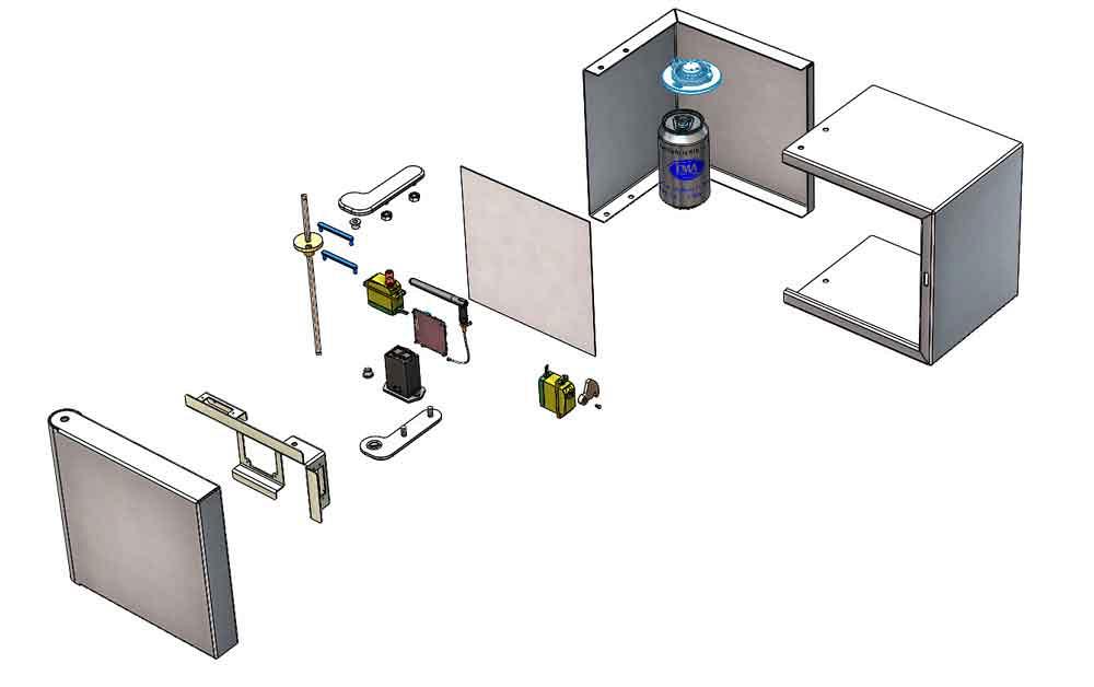
The mechanical plan calls for using an RC servo-motor to push and pull levers to rotate a shaft. Figure 1B reveals the positioning mechanism housed in the door that is attached to a box.
The door mechanism includes a second motor to position a locking latch. The box’s hinge plates (top and bottom) retain the stationary hinge shaft. The motor’s torque against that shaft causes the motor, along with the door, to rotate relative to the box.
Here’s a paper and pencil tip: While planning the geometry, hold the door stationary and move the box relative to it. This can otherwise feel a bit like patting head while rubbing tummy.
The electrical plan is not our task. Simply imagine that radio waves (Wi-Fi, 50-Hz, RC, etc.) and some sort of control board exist. An example board is shown for mechanical planning only. Your design will have to incorporate details of electrons and software.
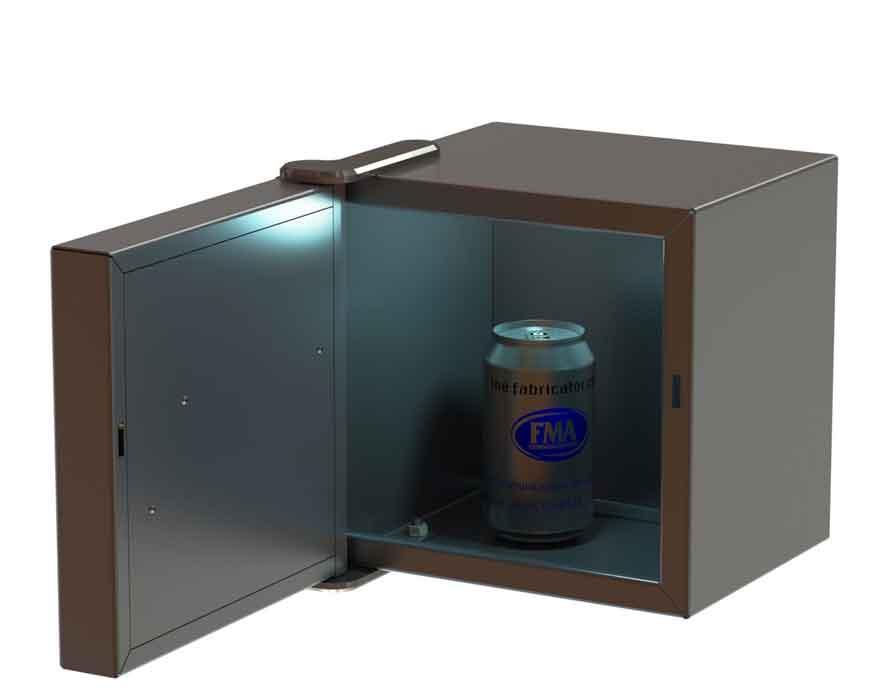
Figure 2A shows the FMA IoT box in full dress. There is an interior light, of course. Does the light go out when the door is closed in Figure 2B? You could download the 3D CAD for this project to verify that.
Matryoshka, also known as nested dolls, are a metaphor for the relationships between the components in this project. As the smallest matryoshka, the two box wall parts—the L-of-2 walls and a U-of-3 walls—are modeled in reference to planes to define their size. Those planes reside in a third component living in the assembly.
The next nest adds mounting holes, hinge plates, and nuts to the box. The bottom hinge plate is mirrored, at this assembly level, from the top hinge plate. A similar assembly nests all of the door’s parts into a little, albeit stuffed, matryoshka.
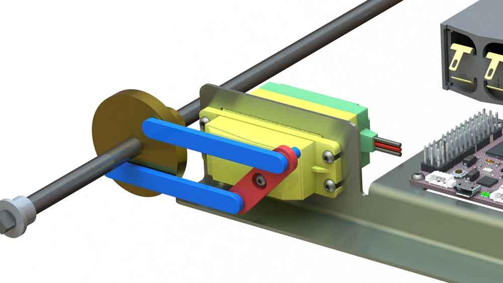
Figure 1a
A radio control servomotor is connected with levers to rotate a hinge axle.
The next nest is the IoT box that will go to production. It’s an enclosure with a working kinematic door. And the biggest matryoshka is documentary evidence presenting the IoT box and its contents. In this demo, the IoT box guards the FMA Can of Do.
Reference planes are used to control size. This CAD technique also works well for controlling 3D sketches for weldments, but that is another topic. The reference plane model takes a few moments to set up, but does allow for convenient shape change during research and development.
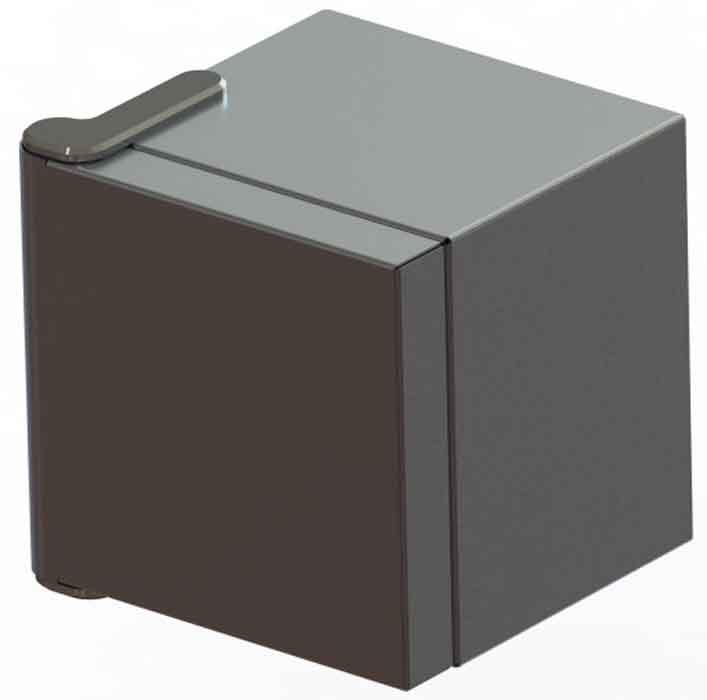
The FMA IoT box is shown as a 9-in. (23-cm) cube. Move a plane and the box/lid will change shape at the next rebuild.
Here’s a CAD tip: Drag the top plane down to create a bottom plane, and drag the right plane to create a left. It can be confusing to edit anti-intuitive modeling where the top plane is functionally the floor and the right is on the left.
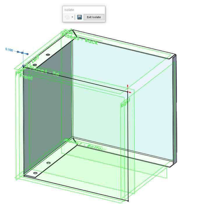
These reference planes exist in an otherwise empty master part model. All sketches to be linked to those planes are drawn in the context of an assembly that includes the master part. Figure 3A shows sketching in progress.
This CAD trick, using a common reference-plane-model in subcomponents, is often useful in projects where the entire top-level assembly model cannot be opened because there’s just too much CAD data to fit into memory (see Figure 3B). In such a project, each subcomponent is modeled to be opened in isolation. Each subcomponent includes a copy of the master reference plane model.
Even though the components will never see each other, they always match the same reference part and thus fit together in future reality. We are stretching a bit to use this technique in such a simple project, but we do it for two reasons:
The benefits of referenced planes are that they are fast and reliable. The plane’s demand on CPU time is minimal. It has no mass, so it doesn’t affect inertia study. Also, the part that contains it can be excluded from the bill of materials (BOM), so it doesn’t mess up production planning. In this demo, reference planes are used to constrain sketches for both the lid and the box simultaneously. In result, they should always fit together nicely.
What are the penalties of planes? If the referenced model is moved in space, you find that each time the assembly is rebuilt, the components that reference them—lid and the box—will exist differently. (Internal surface IDs for mates may change; they don’t move kinematically relative to each other.)
In this demo, the lid must open and close relative to the box. Moving planes to force a lid to rebuild in a different location is intense and slow CAD. Moving planes to alter shape is useful, however, when making Motion Study animations of flexing springs. But that is not our goal here.
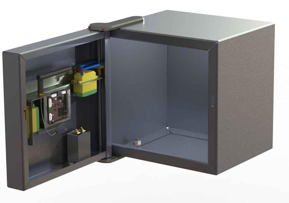
Figure 1b
The positioning mechanism is housed in the door. The hinge axle is stationary, and the motorized door moves relative to it
Alternatives to planes-only construction include the use of any available surface, edge, or vertices for reference geometry. The penalty may be that the referenced model adds mass and BOM to the project. One could work around those issues with appropriate Exclude From BOM settings and suppression of redundant components during Simulation Studies. The well-oiled CAD jockey has a mighty click at the ready.
The Envelope setting is a way to transform any component into a BOM-less and massless reference model. (Right-click on a component, select Properties, set to Envelope.) Because of their potential to confuse the unaware, Enveloped parts have a distinctive appearance.
To clarify the matryoshka song and dance, the box model defines the lid in the closed position. The lid part changes shape with the box if it changes. Note that in this assembly, the lid never pivots relative to the box, it just stretches during R&D of the box.
Here’s a fancy trick: The lid part is set to Envelope in the box’s assembly so that the box model just behaves as a box without a lid. The equivalent to Envelope is Exclude From BOM, assign mass=0, and set the appearance to transparent cyan.
In preparation for kinematics, a door assembly is modeled separately from the assembly for the box. The door assembly includes a copy of the sheet metal lid, the servos and levers, battery, pulse width modulation board, and wire.
In preparation for real-time presentation of this project, the door assembly has two configurations: open and closed.
Functionally, they rotate both the hinge axle servo and the latch/lock servo.
To make a kinematic swinging door, a box and door assembly is modeled. In this assembly, the door’s axle is mated rigidly to the hinge plates on the box. The Selecting the Open configuration of the door assembly will appear to move the door 90 degrees relative to the box.
Selecting the Closed configuration rotates the hinge axle in the door assembly. Because the hinge axle is stationary relative to the box, the door moves (instantly) to the closed position. So now you know how to Envelope.
Author’s note: Dear The FABRICATOR, congratulations on your 50-year legacy of monthly celebrations of manufacturing in the U.S. People applying technology to produce great products makes for fascinating stories.
Also, thank you, dear readers! For about 20 of those 50 years, my musings about how I make a living in manufacturing have been carried in these pages. It would not be possible without an audience.And hurrah for the editing patience and skill of Amy Nickel, Kate Bachman, and Dan Davis in making my technobabble readable.
Gerald would love for you to send him your comments and questions. You are not alone, and the problems you face often are shared by others. Share the grief, and perhaps we will all share in the joy of finding answers. Please send your questions and comments to dand@thefabricator.com.


The Fabricator is North America's leading magazine for the metal forming and fabricating industry. The magazine delivers the news, technical articles, and case histories that enable fabricators to do their jobs more efficiently. The Fabricator has served the industry since 1970.
start your free subscription
Easily access valuable industry resources now with full access to the digital edition of The Fabricator.

Easily access valuable industry resources now with full access to the digital edition of The Welder.

Easily access valuable industry resources now with full access to the digital edition of The Tube and Pipe Journal.

Easily access valuable industry resources now with full access to the digital edition of The Fabricator en Español.
In this episode of The Fabricator Podcast, Caleb Chamberlain, co-founder and CEO of OSH Cut, discusses his company’s...


