


Contributing Writer
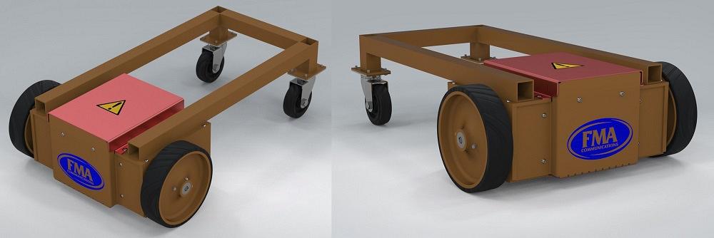
FIGURE 1. This design has evolved to the mature concept stage. It is now time to document it for fabrication.
Editor's Note: If you would like to download the 3D CAD files associated with this column, click here.
Figure 1 is a rendering of a CAD project, a motorized base for a shop cart. This design has progressed to a mature concept stage. After a design review in the previous episode of this column, the immediate task is to ready this design for release; that is, create documentation for fabrication.
The firm that is sponsoring this product line is a startup company staffed with visionaries and accountants. They are new to CAD, subcontracting, and all aspects of owning a product line. Of course, the business, its mission, and most of the scenario we are presenting are imaginary. The labor described is real. We’re trying to avoid the disclosure of proprietary information. Any resemblance to an actual product or company is remarkable, and we do not mean to intrude on their business.
CAD software simply creates and maintains a database. The entertaining aspect of the software is a sideshow that helps us visualize what’s in the database. The activities and design decisions, along with the corporate standards for drafting and reporting, strongly influence the operation of the CAD software.
Every startup I’ve worked with has been surprised at how many forms, templates, logs, and standards are needed just to pass go.
Logging activity—knowing who worked how much on the project—is largely a distraction from creativity, but it is necessary. As a timecard, it pleases the accounting people. It keeps track of the person responsible for future design decisions and is a form of speedometer for the project.
The activity log shown in Figure 2 is basically the project’s diary organized for review and analysis. In the absence of a document control system with good reporting like product data management, a spreadsheet can suffice for keeping track of who edited what.
The TAG column in our example activity log summarizes the activity into a word, such as research, admin, CAD, or daydreaming. As the project matures, it is informative to chart this spreadsheet (sorted by TAG) to consider how time was spent. If a great deal of time is spent on daydreaming, an opportunity for more directed work assignment might have been found.
The labor of time accounting can be distracting. Timing and recording of when a thought came and went are antithetical to creativity. Notation of best recollection of events is the plan. One of the goals for time-logging is to gain the ability to predict how much time the next project is likely to take. Of course, the costing of the project will rely on activity reporting as well.
The distinction between tags like CAD and RESEARCH might be related to the kinds of software used. As an independent contractor, I maintain software licenses; this is a business expense that is to be limited. A review of activity logs reveals the frequency of use of various tools. Over the years, I’ve pruned a few licenses after reviewing my activity logs. If you don’t use it, lose it. Conversely, if you’re not using an available tool, why not?
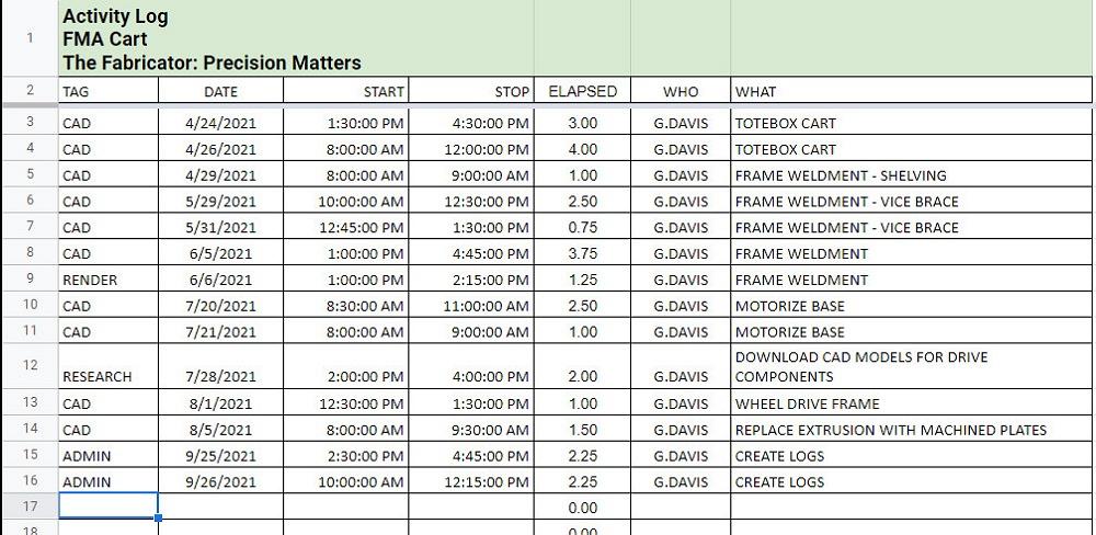
FIGURE 2. The activity log is basically a timecard for the project. If a vault is in use, it can generate reports of similar nature.
In the example log in Figure 2, notice a column for WHO. It is suggested here as perhaps one of many ways to create a better activity log. WHO is more often a data element reported by the vault rather than an entry in a manually prepared spreadsheet. The CAD/Vault reporting can save labor in activity tracking. It automatically tracks who did what.
Working with a vault is strongly recommended, not just for activity reporting. Security and access control are vital in a collaborative project. Using the workflow and signoff controls that the vault offers can help manage grief in a chain of authority to tolerable levels.
In addition to using a CAD vault, spreadsheets also are recommended for activity logs because they are easy to share and to tailor on a project-by-project basis.
The WHAT column in the activity log, like the TAG column, benefits from brevity—a one-line response to the query from the bored “What did you do today?” As the activity log is reviewed, the goal is to verify that labor is going to good use, not necessarily to understand the achievement and satisfaction of each session. That is what the engineering change log is for.
Mistakes happen. Figure 3 is a screenshot of the FMA cart’s engineering change (EC) log. The main purpose of the change log is to record the permission granted and the action taken in revising the design. It also provides room for narrative regarding the revision task. The revision table on the drawing has limited space; the log has bountiful space.
Figure 3 has emphasized EC0004 to demonstrate the difference in purpose between the description entry in the revision table and the task entry in the EC log. The inset image in Figure 3 highlights the corresponding REV C entry in the revision table found on the fabrication drawing. The task notation in the EC log can and should be as verbose as practical to describe the intention of the change.
Such activity and change logs have proven to be useful for training and orientation. When new talent is brought into a project, a scan through the tasks, both completed and pending, provides insight and grounding in the project.
This example of a change log spreadsheet uses conditional formatting (green background) to indicate tasks that are complete. This eye candy has proven to be useful when scanning the log for pending activity.
An omission in the log in Figure 3 still needs to be corrected. The inventory of affected files is incomplete. We note in the inset image that the drawing’s REV C was triggered by EC0004. When EC0004 was marked as closed, the file name of the sldasm was noted. That’s good. However, the slddrw and the released REV C.PDF were not recorded. That’s an omission.
Before part numbers and descriptions can be assigned to the concept model and its components, a part number log is needed. As a side note, a vehicle identification number (VIN) is coded so that a great deal of meaning can be derived from the part number. The numbering system used here is far less ambitious but does have some meaning built in.
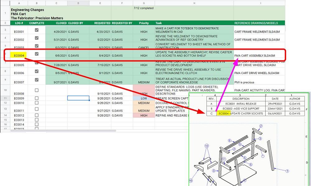
FIGURE 3. This engineering change (EC) log uses conditional formatting to turn completed tasks green. This helps us to identify the pending change orders. The EC log is verbose and chatty; the revision table is succinct and brief. The completed log entry should indicate the released revision. This example fails to do that. (See the purple arrow.) Tsk. Tsk.
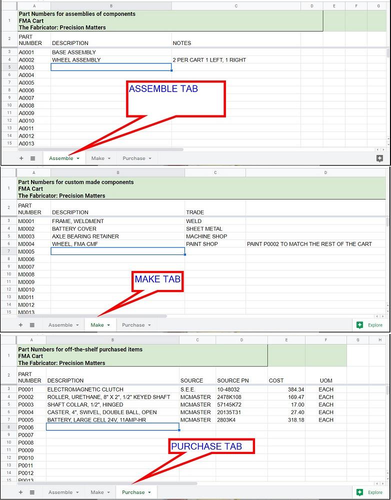
Figure 4 shows the AMP method that will be used for this project. Purchased items, P, are taken to mean off-the-shelf. If one must make the item from scratch, it gets an M. If the item is assembled, usually in-house, then its part number starts with an A.
The part number log has two main consumers—the CAD team and the purchasing department. The entries for cost on the Purchased tab are obsoleted as soon as they are entered but do provide a reference for the next design review meeting. The entries for TRADE on the Make tab help purchasing sort out who to send the RFQ to. It may be hard to read, but M0004 is a wheel that is made from a purchased item, P0002. The approved colors, materials, and finishes apply to the drive wheels, so the off-the-shelf item must be repainted to match the cart.
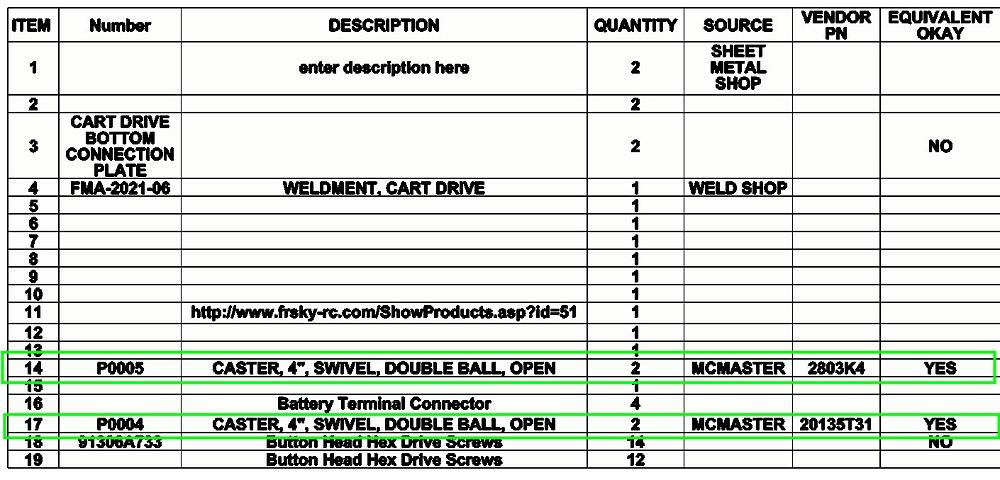
A messy and incomplete BOM table is shown in Figure 5. Only two out of 19 rows are correct. Item 14 is P0005 and has been assigned to 2803K4, and item 17 has the alias P0004 for 20135T31. The rest of the table represents a data retrieval and data entry task. Product manufacturing information, or PMI, is one of our most valued deliverables. Efficient 3D modeling and lovely 2D drawings are among the deliverables.
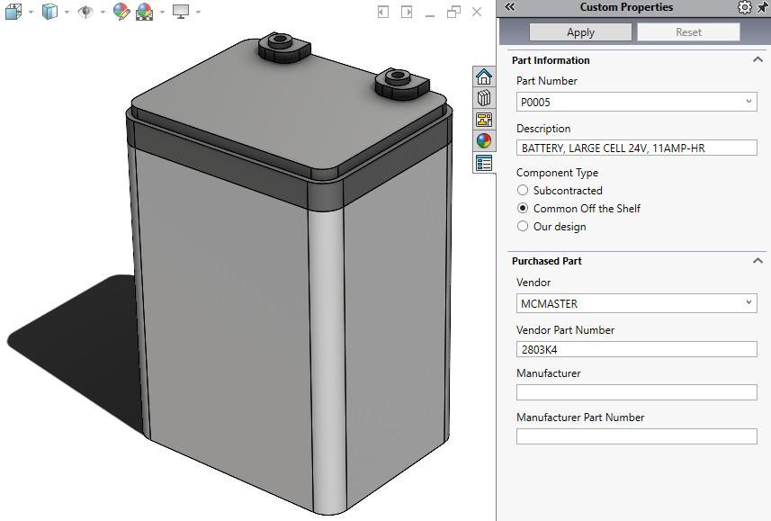
The data entry in 3D CAD goes much faster using a properly designed form on the Custom Properties flyout. An example is shown to the right in Figure 6. Prepping the CAD includes creating the sheet templates, BOM table template, REV table template, and drawing templates. Designing these templates could be a topic of future episodes. Drop us a line.
The next episode will turn to setting up a few folders for file sharing. Perhaps the 2D drawings will get a start. Almost certainly the design will change as details are resolved.


The Fabricator is North America's leading magazine for the metal forming and fabricating industry. The magazine delivers the news, technical articles, and case histories that enable fabricators to do their jobs more efficiently. The Fabricator has served the industry since 1970.
start your free subscription
Easily access valuable industry resources now with full access to the digital edition of The Fabricator.

Easily access valuable industry resources now with full access to the digital edition of The Welder.

Easily access valuable industry resources now with full access to the digital edition of The Tube and Pipe Journal.

Easily access valuable industry resources now with full access to the digital edition of The Fabricator en Español.
In this episode of The Fabricator Podcast, Caleb Chamberlain, co-founder and CEO of OSH Cut, discusses his company’s...


