


Contributing Writer
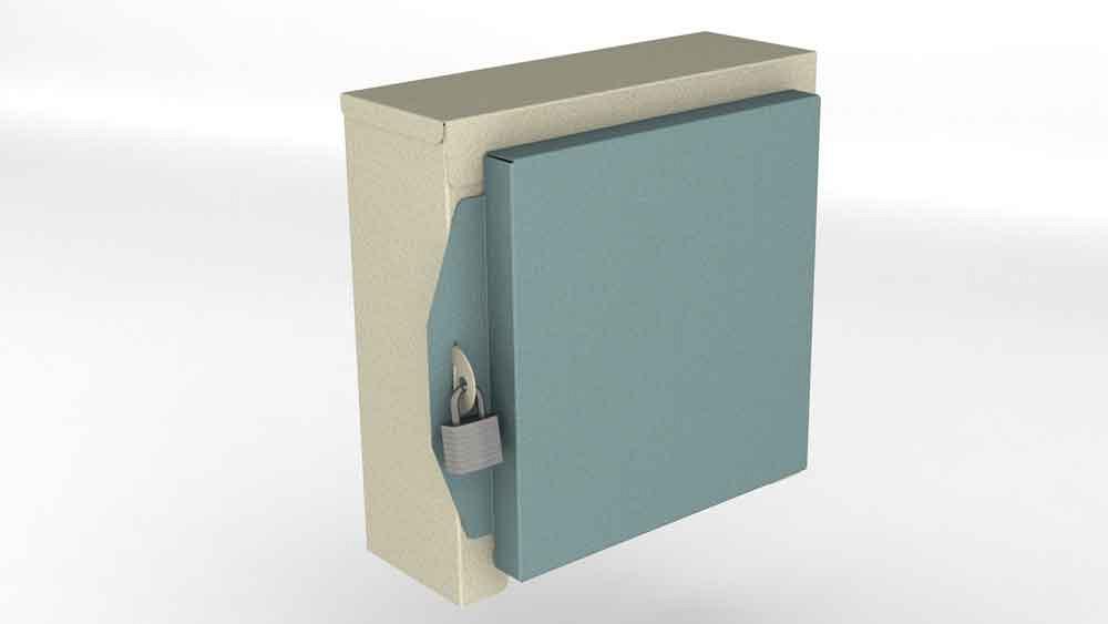
Figure 1A
Editor's Note: If you would like to download the 3D CAD files associated with this column, click here.
Part marking helps with auditing when dealing with inventory. In this article, the part marking identifies the drawing and the revision that controlled the fabrication of an item.
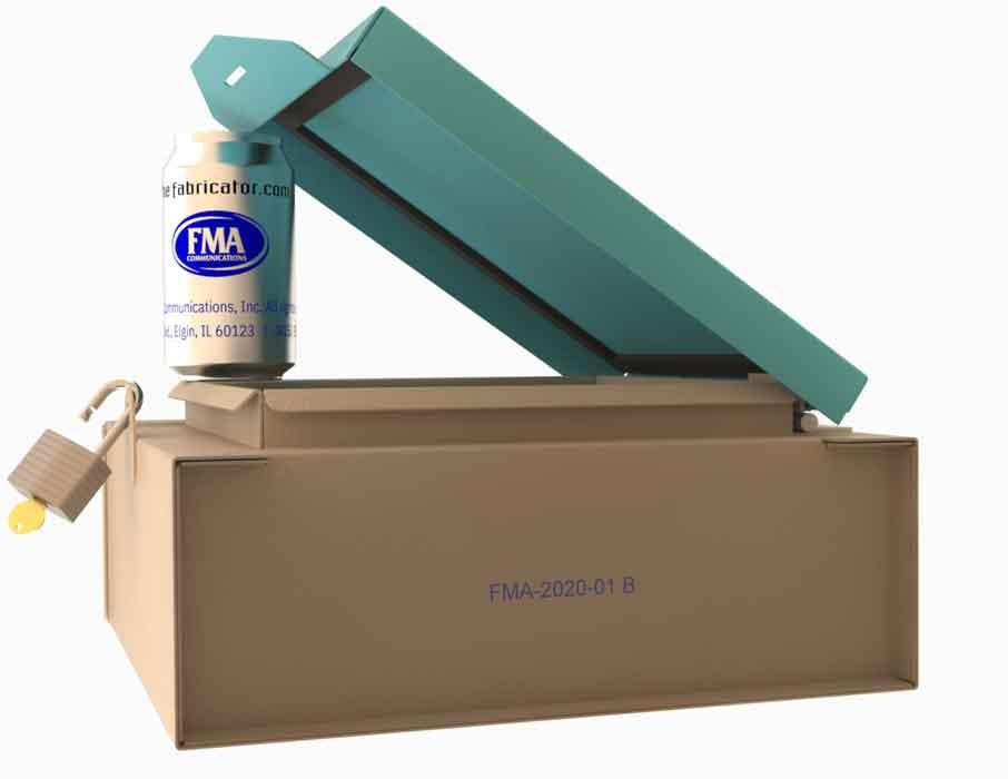
The enclosure shown in Figure 1a lacks part marking. However, Figure 1b does show the use of a JPEG image as a decal on the FMA can. Decals are always an option for part marking.
In general, part marking is accomplished by indelibly recording the part number and revision on some surface of the part. The part marking could include additional information such as date and location of creation.
The part marking process might be as simple as writing the information by hand with a felt-tipped marker. Various forms of engraving may be suitable. Part marking could be as elaborate as screen printing in multiple colors. In batch production, the marking is typically performed with metal stamps or laser etching.
Several options for modeling and documenting part marking features using mainstream 3D CAD are available to CAD jockeys. In this month’s episode, the task is to specify part marking for the enclosure shown in Figure 1.
Figure 2 shows the first sheet of a multisheet drawing that documents the fabrication of the example enclosure. Frequent readers may recognize the BOM table and balloons as topics of previous episodes of this column.
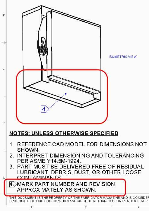
Figure 3 is a close-up of the notes from Figure 1. The part marking is specified in Note 4: “Bag and tag with part number and revision.” The advantage of this from the CAD perspective is that it is simply easy. The disadvantage of bag-and-tag is that once the packing material is removed, the part’s provenance is lost.
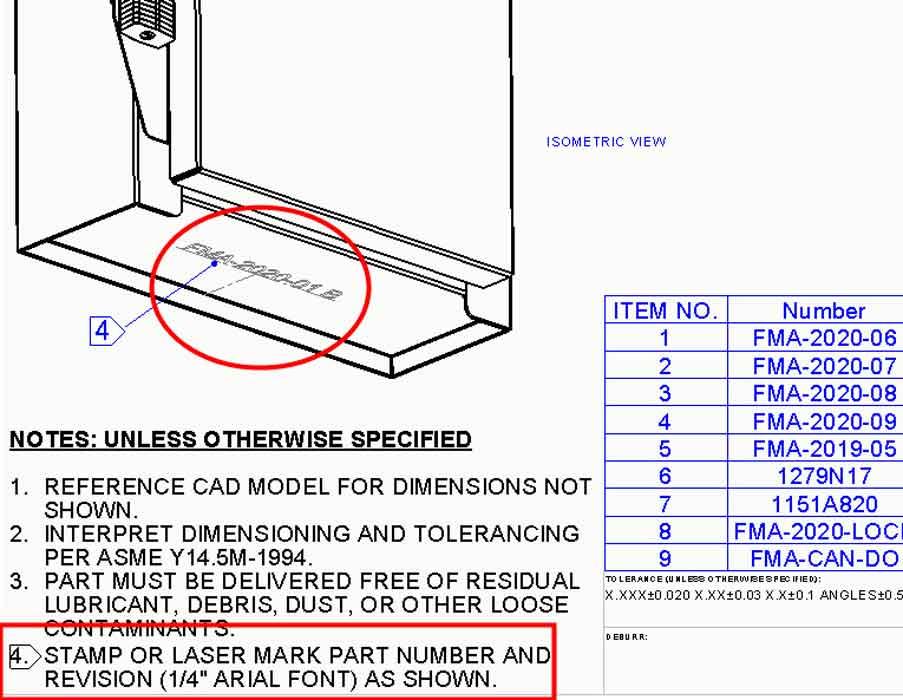
Figure 4a is a variation on Note 4 that attaches the part marking to the part instead of to the packing material: “Mark part number and revision approximately as shown.” Here, a view of the part indicates where the part marking should be. The word approximately allows latitude to the fabricator as to process, color, font, and size.
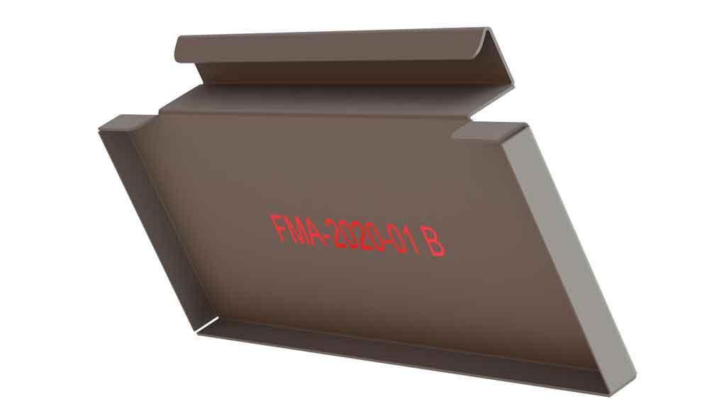
That latitude might result in lowest cost for such markings. Figure 4b shows an example of dramatic part marking that complies with Note 4. It is likely that ambiguous specification will result in a variable appearance in part marking from batch to batch.
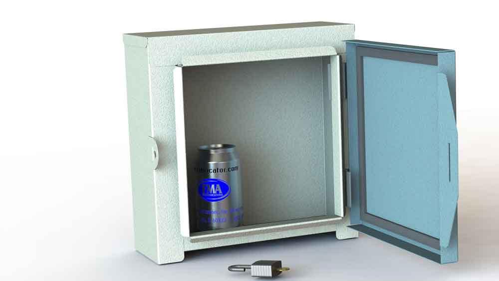
Figure 1B
A surprising result in part marking is not usually desired. For easy planning and clear visualization, a CAD jockey should model the part marking not as a simple note or sketch, but rather as a modeled feature.
If the part is laser-marked or stamped, then a cut-extrude is good. If the part marking is to be ink-stamped or screen-printed, then a boss-extrude above the surface would be a good representation.
Figure 4c shows our ideal part marking on the finished assembly. It is obviously there if you look for it, but otherwise is not obtrusive. The best method of modeling this part marking depends on intent. In this scenario, the intent is for the part marking to represent the entire enclosure. The revision is for the weldment, not necessarily for the components that are in the weldment.
In an alternative scenario, each individual component that makes up this assembly could get its own part marking. In that scenario, the part marking would be modeled in the context of each part. The children have their own revisions.
In this scenario, the children are to get their revisions from their parent assembly. Accordingly, an “assembly feature cut” is used to model the part marking. An extruded cut that is modeled at the assembly level is propagated to the children—in this example, the floor of the enclosure.
Figure 5a is variation on Note 4 that further standardizes the part marking: “Stamp or laser mark part number and revision …”. In this version of the 2D drawing, the isometric view has an option set to show sketches (which are often set to not-visible because sketches are usually sketchy). The 3D model that this 2D drawing is displaying has a sketch showing the location of the part marking.
This 2D sketch for the part marking has a couple of fancy features. One is that the text in the note is linked to the part number and revision of the model, which helps to automate the revision process by auto-updating the sketch as the revision changes. The sketch also includes construction geometry that indicates the placement of the part marking.
Using this specification technique for part marking has two strong advantages:
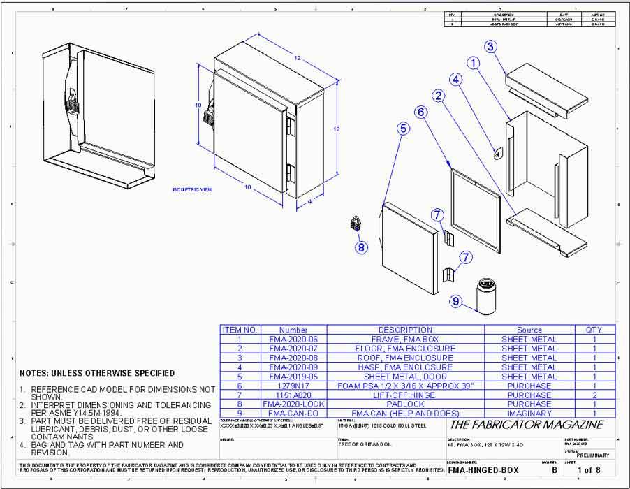
Figure 3
The disadvantage is that it is hard to visualize because the marking does not exist unless sketches are visible, both in the 3D model and in the 2D drawing.
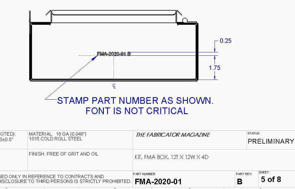
Figure 5b documents (with dimensions and fancy notes) what Figure 4c shows so prettily for part marking. The 3D model uses the 2D sketch from Figure 5a to create a 3D assembly-level cut-extrude.
As mentioned earlier, that assembly-level extruded cut is, by setting, propagated into the children parts—in this example, the floor of the enclosure. The disadvantages of this very visual method of modeling part marking include greater burden on the CPU—more surfaces to render—and occasionally the revision in the linked part marking text sketch doesn’t trigger the extruded feature to get rebuilt until the sketch for the part marking is edited.
Even though it takes an extra mouse click or a few, a CAD jockey will appreciate the goof-proofing advantage to linking the part marking text to the product manufacturing information in the document. It is a visual advantage to see where the part marking will be on the finished product.
Part marking bliss includes using a font that is available to the fabricator. When in doubt, ISOCP is a centerline-only font that is often compatible with CAM software.
Gerald would love for you to send him your comments and questions. You are not alone, and the problems you face often are shared by others. Share the grief, and perhaps we will all share in the joy of finding answers. Please send your questions and comments to dand@thefabricator.com.


The Fabricator is North America's leading magazine for the metal forming and fabricating industry. The magazine delivers the news, technical articles, and case histories that enable fabricators to do their jobs more efficiently. The Fabricator has served the industry since 1970.
start your free subscription
Easily access valuable industry resources now with full access to the digital edition of The Fabricator.

Easily access valuable industry resources now with full access to the digital edition of The Welder.

Easily access valuable industry resources now with full access to the digital edition of The Tube and Pipe Journal.

Easily access valuable industry resources now with full access to the digital edition of The Fabricator en Español.
In this episode of The Fabricator Podcast, Caleb Chamberlain, co-founder and CEO of OSH Cut, discusses his company’s...


