


Contributing Writer
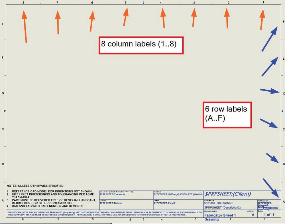
FIGURE 1A. The drawing template is using a 22- by 34-in. sheet size (ANSI C size). That is deemed to be acceptable. The (16-point) font for the zone labels is likewise deemed acceptable. The decision is made to proceed with eight columns and six rows as a zone grid.
Templates in a CAD system affect drawings, parts, assemblies, and various tables and forms. The best templates have professional appearance, save labor, and reduce error. The design of templates is an occasionally used skill, sometimes delegated to the intern.
This specialized effort is intense at the beginning of a project and then becomes a matter of sporadic maintenance. To put it another way, a learning curve occurs early on and is followed by re-learning curves.
Sidebar: A specific brand of mainstream 3D CAD is being discussed. As a matter of information, the add-in Template Wizard for this 3D CAD package is an excellent tool for designing and administering templates. I have no affiliation with that or any CAD product, but I was once fortunate and pleased to be on an engineering team with its developer.
The Template Wizard addresses the seldom-used aspect of template design. The learning curve for the add-in is more about understanding settings to achieve preferences and is less about the nitty gritty syntax of links using custom properties to share product manufacturing information (PMI) between files.
If you administer CAD projects that span turnover in staff and standards, you should at least be aware of the stability and consistency the Template Wizard offers.
For those interested in ad-hoc, nitty gritty, DIY template design, we now refer to a CAD project from previous episodes. In summary, templates from a variety of sources are being merged as part of supporting a new project—the imaginary FMA Cart.
Our drawing template has legacy, not quite as charming as having a fax number, but close. In the olden days before paperless manufacturing became the norm, final drawings were always printed and stored in a flat file.
Part of our template legacy is 22- by 34-in. paper, which matches ANSI C size. Figure 1A gives a sense for the size of text on the printed sheet. If we wanted a different sheet size, we would start with a different sheet format as a starting point.
From previous episodes, we have a good start on a data entry form to collect the PMI. Figure 1B is showing that form’s roll in the path of the description. It starts in the 3D model (PMI is entered and saved via a data entry form) and ends in the 2D drawing (text displayed in the title block). All of our PMI (material, author, etc.) follows a similar linkage.
With the brand of CAD being used, when a drawing file is opened, the drawing’s sheet format will be displayed, with the sheet format guiding the retrieval and display of the PMI found in the 3D model. In other words, the drawing is a container for the sheet format (border) and the various views of the model. There are templates for drawings as well as for sheet formats.

FIGURE 1B. As a policy decision, PMI is entered using a form (center of the image) associated with the component—in this example, the motorized cart frame. A screenshot of the component’s drawing, to the right, is shown to demonstrate the flow of information. The drawing’s template has filled in the description using PMI found in the component.
Sheet formats are protected from accidental editing. Sheet formats are edited much like an ordinary 2D sketch. Completed sheet formats can be exported and then can replace the sheet formats used by existing drawings or drawing templates.
Several CAD-oriented policy decisions guide our design of templates:
From the previous episode, updates are planned for the default notes and, perhaps, default tolerances. We’ll keep those edits on the to-do list. Revision table setup is more entertaining.
A revision table can have easy-to-add columns, fonts set, and widths set, and later can be saved as a template. That revision table template then can be inserted into a drawing template.
Revision tables feature labor-saving abilities. One of those abilities automates the data entry of the zone coordinates on the drawing where revision symbols have been added.
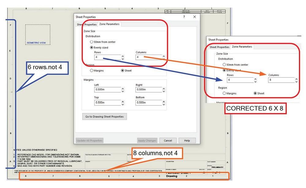
The drawing template we’ve inherited has a discrepancy with zone parameters for the revision table. In Figure 2, the column labels A-F are in a blue box. The column labels 1-8 are in an orange box. It is the quantity of labels, not the labels themselves, that are in error.
In Figure 2, the Sheet Properties dialog is showing Zone Parameters for the revision table, currently set to four rows and four columns. That is corrected to six rows (A-F) and eight columns (1-8).
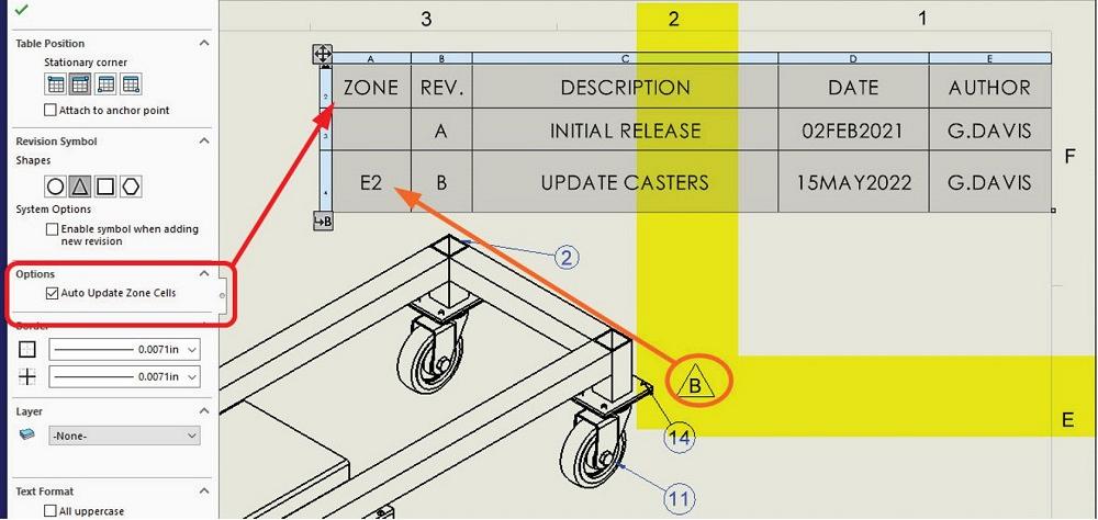
The epiphanous Auto Update Zone Cells setting for the revision table causes the table to automatically update the cells in the zone column based on the locations of the corresponding revision symbols.
In Figure 3, the results of the Zone Parameter setting from Figure 2 are shown. Note the location of the revision symbol (triangle around B) is in the sheet’s fifth row (labeled E) and second column (labeled 2). Thus, zone E2 appears for the REV B row in the table.
As might be noted with the preview of the template in Figure 1A, issues remain with font sizes, notes, and what is or is not PMI. Who needs a property for client? Don’t we know the name that should appear on the drawing?


The Fabricator is North America's leading magazine for the metal forming and fabricating industry. The magazine delivers the news, technical articles, and case histories that enable fabricators to do their jobs more efficiently. The Fabricator has served the industry since 1970.
start your free subscription
Easily access valuable industry resources now with full access to the digital edition of The Fabricator.

Easily access valuable industry resources now with full access to the digital edition of The Welder.

Easily access valuable industry resources now with full access to the digital edition of The Tube and Pipe Journal.

Easily access valuable industry resources now with full access to the digital edition of The Fabricator en Español.
In this episode of The Fabricator Podcast, Caleb Chamberlain, co-founder and CEO of OSH Cut, discusses his company’s...


