


Contributing Writer
Though the U.S. economy continues to struggle to add jobs, manufacturers are increasing productivity with automation and technology. While faced with tightening capital availability, job shops and OEMs continue to add new capabilities to enter new markets. For example, thermal processing equipment such as lasers is being used to cut and weld low-carbon and stainless steels.
As competition between DROID®s and the iPhone®s heats up, so does the need for laser proc-essing of circuit boards and touchscreens needed for each device. The U.S. Navy’s F-18s take off using the thunderous force created by two General Electric F414-GE-400 turbofans generating 22,000 lbf. of thrust each with afterburner. Lasers are used to drill cooling holes in the turbine blades to prevent expansion caused by takeoff and acceleration forces.
With growth markets such as these, metal fabricators must evaluate the laser technology that best fits their specific needs and applications.
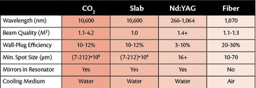
Proven integrated resonator technologies include Nd:YAG (neodymium-doped yttrium aluminum garnet), diffusion cooled (slab), CO2, and fiber. The main differentiating characteristics of the technologies are the lasing medium and cooling method.
Each OEM and job shop must evaluate a resonator’s output and design to determine the best fit for its applications. Resonator characteristics such as beam wavelength and quality, spot size, absorptivity, and operating costs must be considered because they affect productivity and subsequent part costs.
Physical properties of the resonator play a significant role in smallest achievable spot size and subsequent power density (see Figure 1). In Figure 2, Z is the depth of field where the beam diameter is ± 5 percent of the spot size along the axis.
The fiber’s short wavelength yields the smallest spot size. Additionally, with high beam quality M2 and small spot size, the machine tool has a broader depth of field Z, which enables greater process tolerance to material deviations. Subsequently, the operator has a greater sweet spot for machine parameters to produce consistent, high-quality parts.
Two additional factors, absorptivity and incidence angle, also affect power density and productivity.
Power density refers to the resonator’s energy radiant over a given surface area. It can be calculated as Pd = 4P/(3.14D2), where Pd = Power density, P = Power, and D = Density. In general, it is assumed that heating of the material and subsequent travel speed increase with increasing power density. The energy distribution profile as it relates to beam mode, melt viscosity, and incidence beam absorptivity are also factors to be considered.
The lower-order beam mode M2 = 1 yields the highest power density, which is ideal for cutting (see Figure 3). Higher-order modes M2 > 3 yield a wider energy distribution profile, which is better for surface treatments such as welding and heating. Beam delivery systems can also affect the raw incidence beam entering the focal optic.
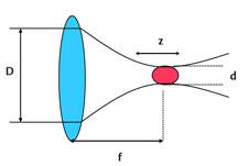
Figure 2: Z is the depth of field where the beam diameter is ±5 percent of the spot size along the axis. D is the raw incidence beam, d is the spot size, f is the focal length.
Fiber-optic delivery provides the most consistent transmission, whereas CO2 resonator output requires a clean, dry atmosphere along the bellows that contain the reflective optics (mirrors). These mirrors have highly reflective coatings, such as zinc sulfide (ZnS) or zinc selenide (ZnSe), that offer good thermal conductivity to dissipate heat, thereby minimizing thermal lensing or distortions. However, they are susceptible to moisture and particle contamination that deteriorate optical performance.
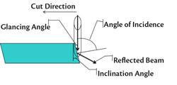
As the focusing lens concentrates the raw beam onto the material, it is absorbed and partially reflected. Absorption is the greatest for a given wavelength of light as it approaches its Brewster’s angle.1 Brewster’s (polarization) angle is the angle of incidence at which light of a specific wavelength passes through a transparent surface without being reflected.2
The maximum absorptivity of wavelength 1.075 by 10-9m, which occurs at Brewster’s angle or 10.4 degrees of the cut-face inclination3 (see Figure 4), enables full illumination of the beam diameter and maximum melting of material. The elevated melt temperature, which minimizes viscosity, allows higher melt velocity and subsequent travel speeds. The longer CO2 wavelength and subsequent larger spot size cause the optimal angle of inclination to be closer to 3 degrees, which is steeper than the fiber laser, and minimizes the interaction of the beam diameter with the cut face for thin materials.4
Fiber lasers also have higher wall-plug efficiency, and the resonator can be air-cooled because of the high surface area of the cable itself. However, the higher travel speeds on thin material put greater demands on the assist gas delivery system. The role of the assist gas is to evacuate the molten material. Oxygen as the assist gas contributes an additional 40 percent heat input because of the exothermic reaction occurring with iron.
Liquid cylinders are capable of continuously delivering only 200 cubic-feet-per-hour (CFH) gas phase (see Figure 5). When materials require higher flow rates, cryogenic cylinders can be manifolded to deliver liquid phase into a vaporizer, enabling equivalent gas flow rates of 600 to 700 CFH per cylinder. Safety relief valves must be installed where liquid can be trapped.
It may be necessary in a multiple-shift schedule, or whenever a bulk tank is not viable, to use a switchover to provide a continuous supply from two separate cylinder sources. This type of switch-over minimizes gas loss while allowing a delivery pressure closer to the maximum rating of the liquid cylinder.
On thin materials, fiber lasers are capable of higher travel speeds because of their shorter wavelength. This leads to greater absorption and subsequent power density from the smaller spot size. However, as thicker materials are processed, the larger-diameter CO2 beam has the advantage of illuminating the entire cut face with slightly wider kerfs that enable better melt flow.
With capital for metal fabricators remaining tight, the selection of the best resonator for the application can be more complex than choosing a Droid or an iPhone.
Notes
1. S.O. Al-Mashkkhi, J. Powell, A.F.H. Kaplan, K.T. Voisey, “An Explanation of ‘Striation Free’ Cutting of Mild Steel by Fibre Laser,” in proceedings from 5th International WLT-Conference on Laser in Manufacturing, Munich, June 2009, www.laserexp.co.uk/consultancyexpert-witness/laser-science.
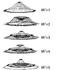
Figure 3: Beam divergence of M2=1 with the highest power density is ideal for cutting. M2>3 with wider energy distribution profiles are better for surface treatments such as welding and heating.
2. Brewster’s Angle, Wikipedia, http://en.wikipedia.org/wiki/Brewster%27s_angle.
3. Al-Mashkkhi, et al.
4. Ibid.


The Fabricator is North America's leading magazine for the metal forming and fabricating industry. The magazine delivers the news, technical articles, and case histories that enable fabricators to do their jobs more efficiently. The Fabricator has served the industry since 1970.
start your free subscription
Easily access valuable industry resources now with full access to the digital edition of The Fabricator.

Easily access valuable industry resources now with full access to the digital edition of The Welder.

Easily access valuable industry resources now with full access to the digital edition of The Tube and Pipe Journal.

Easily access valuable industry resources now with full access to the digital edition of The Fabricator en Español.
In this episode of The Fabricator Podcast, Caleb Chamberlain, co-founder and CEO of OSH Cut, discusses his company’s...


