


Senior Editor
When you think about it, assist gas isn’t the best name for something so central to laser cutting. It’s more partner than assistant, working in tandem with the laser beam.
Assist gas sounds straightforward enough: It aids cutting via an exothermic reaction (with oxygen) and evacuates molten material. It’s so straightforward that, according to sources, many new operators don’t think to adjust it when they get a bad cut. They might simply slow the feed rate, which solves the problem, but it does increase cycle time and can negate the reason your shop invested in a laser in the first place: to cut a lot of parts extraordinarily quickly. The problem could have to do with assist gas pressure, which an operator can change easily at the controller; or flow rate, which depends on the nozzle orifice diameter. Or it could be that the focal point needs adjustment. Or the beam may not be centered in the nozzle. Or it could be a combination of everything.
“Assist gas is one of the prime movers and shakers of laser cutting parameters,” said Mark Mercurio, applications and technical support manager for Mazak Optonics Corp., Elgin, Ill.
When troubleshooting a bad cut, ask questions, and when it comes to assist gas, those questions should follow the gas’s journey—from initial delivery to the plant, into storage, through plumbing, into the cutting head, through the nozzle, and into the cut.
Assist gas choice—be it oxygen, nitrogen, or air—hinges on an analysis of manufacturing cycle time versus the cost of the gas. Thanks to its exothermic reaction, oxygen cutting allows the laser to cut thick material efficiently with relatively low laser power and low gas flow, yet the oxide edge needs to be removed if the parts are headed for welding and (especially) painting. Cutting with nitrogen produces no oxide edge, but with its high pressure and flow, clean cutting with nitrogen requires a lot of assist gas.
Conventionally, oxygen assist gas is used on mild steel, though its use on nonferrous material isn’t unheard of, especially if the operator has limited laser power and uses oxygen to stimulate the cut.
“You can use oxygen on stainless and aluminum too,” said Jeff Hahn, national product manager at MC Machinery Systems, Wood Dale, Ill. “Back in the 1990s, when machines didn’t have enough power to cut stainless efficiently, I remember cutting half-inch stainless with oxygen on a 1,000-watt system.”
He added that oxygen cutting stainless has become rare, simply because higher laser powers make clean cutting with nitrogen more attractive, offering competitive speed and eliminating the need for oxide removal.
Oxygen can also produce a higher speed when cutting aluminum, Hahn said, who added that the gas tends to work well with the high absorbency characteristics of the fiber laser’s 1-micron wavelength. “Oxygen is stimulating the cut,” he said, “versus nitrogen, which is suffocating the cut.”
Cutting with air has become more popular through the years, though upfront expenses for specialty equipment, to ensure that air is delivered as clean as possible and with sufficient pressure, can be high. “Air is mostly nitrogen, so it’s inert,” Mercurio said, “but you do have other elements in the mix. That’s why people use it primarily on thin material, where there’s not much of an edge to look at. Also, you still need to have high pressure and high flow, so the typical air coming from a compressor might not have enough pressure to cut cleanly.”
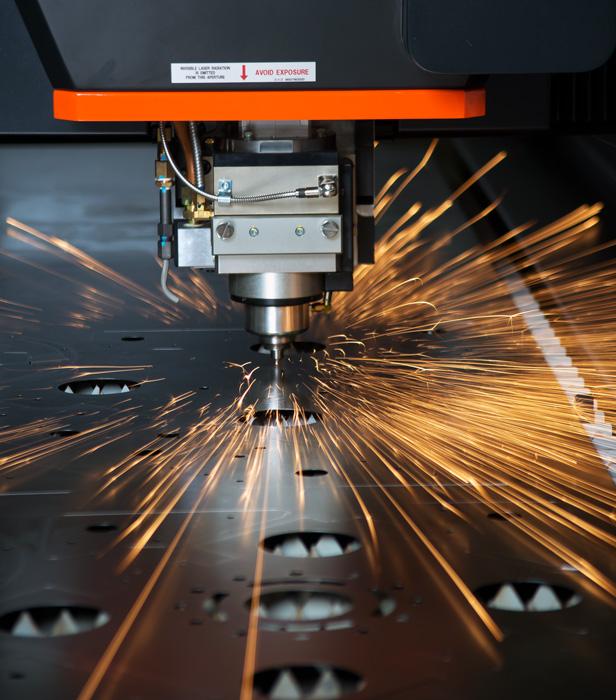
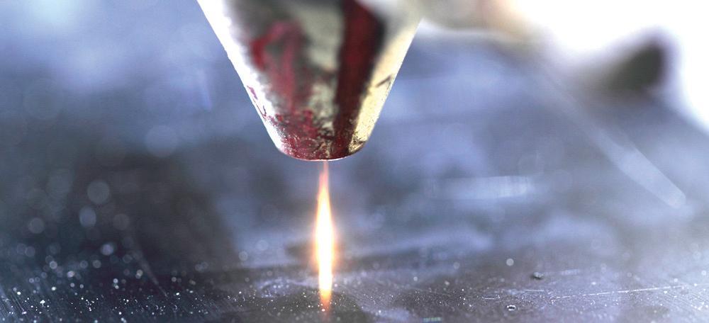
Photo courtesy of Mazak Optonics Corp.
Still, air sometimes has beneficial effects. Laser cutting aluminum with air, for instance, often produces a clean-looking edge. “That little bit of oxygen in the air gives aluminum cutting a little extra punch,” Mercurio said, “and changes what the edge looks like.”
Mercurio added that most gas suppliers deliver purity levels high enough for clean nitrogen cutting, well above 99 percent. “With nitrogen, I’m not so much worried about the purity of the gas being delivered, as long as that purity level doesn’t change. Nitrogen is an inert gas, so you’re just trying to stop any external contaminants and debris from getting into your gas line. But when you oxygen-cut, the closer to 99.9 percent pure gas that you can get, the better off you are. Once you drop the purity below 99.7 percent, you almost stop cutting.”
Gas can be delivered via cylinders (common with oxygen, used in lower volumes), dewars, microbulk, and bulk tanks, with external vaporizers to ensure enough of the liquid gas can be converted to gas at sufficiently high flow rates typical of nitrogen cutting applications.
Volume. “The job of the vaporizer is to produce volume; they aren’t designed to increase pressure,” said Larry Cherne, information technology executive for Praxair, Danbury, Conn. “But if you have the volume, you’re going to maintain the pressure you set. The only way you can build pressure is to use a high-pressure tank or an external device where you trap the liquid in a controlled process and meter it out to maintain a certain level, say, at 400 PSI. ”
Such systems also help maintain flow even when the tanks are being filled. Traditionally a 24/7 operation has used separate tanks, so that one tank is always online to feed a laser. Some shops instead are now using systems that isolate the bulk tank to ensure constant pressure is being delivered to machinery.
“A low-pressure bulk tank feeds into a system that has a 2-cylinder, 4-stroke engine that builds pressure up to 550 PSI,” said Tim Neeser, vice president of marketing and applications development at Chart Industries Inc., New Prague, Minn. “When the driver comes in with the nitrogen delivery, he can deliver into that bulk tank and not disrupt the supply to the application. It can still pull low-pressure liquid off the bulk tank while you’re filling it.”
Plumbing. Cutting with nitrogen calls for a significant amount of gas flow, so the lines feeding in from the tanks to the laser need to be of sufficient diameter to avoid pressure drops. “We call it a pressure drop,” Cherne said, “but it’s really a flow restriction.”
Ideally, the plumbing shouldn’t have an excessive number of 90-degree elbows but instead have sweeping curves wherever possible. The flow also should be sufficient to serve all the laser cutting machines connected to the gas line. And the regulators need to be big enough to handle the flow rate. Sources also noted to pay attention to the pipe brazing. If a nitrogen purge wasn’t used when the line connections were brazed, contaminants from that brazed joint eventually can find their way to the laser.
“If you don’t backpurge with nitrogen when you braze it, the gas line will be full of ash,” Cherne said.
Examine the ports and fittings, especially if a line is being stepped down to a smaller inside-diameter (ID) line. Ensure that smaller-ID line is large enough to support the nitrogen flow needed for the laser cutting application.
Photo courtesy of MC Machinery Systems Inc.
Say you have a 1-in.-diameter nitrogen line feeding the system, and you step it down to a 0.5-in. hose. “The fitting that goes between may be much smaller,” said Cherne. “So you may have a 0.5-in. hose, but the fitting that’s used is only 0.375 in. and so now you have a choke.”
A fitting used to connect the nitrogen line into the laser may create another choke. “So you have a river [of nitrogen] that’s getting smaller and smaller,” Cherne said, “and so you can’t get volume.” He added that when a laser operator isn’t getting enough gas, he turns the pressure up. Ideally, though, those choke points in the assist gas line need to be fixed.
Nozzle. Maintaining gas volume is becoming particularly important when cutting with narrow kerf widths, common in fiber laser applications. Using a wider nozzle diameter seems to benefit a nitrogen cutting operation with a fiber system. To cut 0.25-in. material in CO2 may call for a 2.5-mm-diameter nozzle; but because in a fiber laser cutting situation the kerf is usually narrower, the application may require a 3-mm-diameter nozzle. A 2.5-mm nozzle may require 2,000 cubic feet per hour (CFH), and the 3-mm nozzle may have a gas flow rate of 3,500 CFH. “But if you have a fitting designed for the gas flow from that 2.5-mm nozzle, you’ll have a problem,” Cherne said.
(Sources added that although fiber lasers do use more assist gas, that increased cost is far outweighed by overall increases in cutting throughput, especially in thin material.)
Admittedly, this is a bit counterintuitive. Shouldn’t a narrower kerf call for a narrow jet of assist gas? According to Cherne, the fact that narrow-kerf applications benefit from larger nozzles has to do with friction with ambient air. Imagine a column of nitrogen assist gas descending toward the sheet metal surface. Near the edges of that column, molecules in the fast-moving assist gas flow against slow-moving ambient air molecules. This friction between relatively stationary air molecules and the assist gas sends oscillating waves through the assist gas column.
In a narrow gas column (produced by a small nozzle orifice), these oscillating waves may make it into the kerf and lead to a rough cut edge. With a wide gas column, most turbulent gas molecules never make it to the center of the column. So the assist gas near the center enters the kerf with its flow unaltered for the most part, while the turbulent assist gas never makes it into the kerf and dissipates.
Cherne used a highway analogy. If you have four lanes of traffic, all the cars are cruising along. “Now you all go into one lane, a narrow kerf. The pressure on you is higher. When the kerf is narrower, the spot size is smaller, and when we send the gas through the kerf, we see the friction effects go up. So we compensate for that with a larger nozzle.”
A larger nozzle can give operators a larger parameter window. As Mercurio explained, one nozzle size may allow the operator to cut cleanly between 70 and 80 IPM, while a larger nozzle might allow the operator to cut between 60 and 90 IPM. More gas volume isn’t necessarily better for every application, but it does give the operator more leeway on other parameters.
Still, increasing the nozzle size by even half a millimeter uses a lot more assist gas, and those costs can add up over time. Increasing gas flow can help improve the cut edge, but all that extra gas usage also makes the laser cutting process more expensive.
“We try to use the smallest nozzle diameter that we can to achieve a competitive speed,” Mercurio said, adding that in the standard assist gas flow rate formulas, the nozzle diameter is squared. “If you make a change in the pressure, you make only a small change in the flow rate. But if you change the nozzle size, you’re making a huge change in the flow rate.”
Cherne put it this way: “When you increase the nozzle diameter, the flow goes up, but it makes it easier for the operator to run the laser at a lower pressure. But what is lost in the formula is the flow rate. The typical laser system doesn’t have a flowmeter. So when you change the nozzle diameter, you change the flow. When you change the pressure, it’s a linear rate. If you increase your pressure by, say, 2 bars, and you were at 10 bars, you pretty much know that was a 20 percent change in pressure. There’s a direct relationship. But if you change from a 2.5- to a 3.0-mm nozzle—that’s only half a millimeter. Who cares? Well, in reality, you just about doubled your assist gas flow. But we often do that because it gives you a larger operating window, and you don’t have to operate at such a high assist gas pressure.”
This isn’t a natural question to ask, but it’s one that applies to tuning the cutting conditions. No laser cutting variable acts in isolation. In his book Using a CO2 Laser in the Shop, David Marusa describes optimum cutting conditions with a bowl metaphor. With all parameters tuned for the material and thickness at hand—including feed, assist gas pressure, assist gas flow, laser power, and focal position—the points for all those variables align at the center of the bowl. Change one condition, and it and other conditions move away from the center.
When conditions are set well within safe limits, the bowl has a somewhat flat bottom for the most common material types and thicknesses. The variables (represented by points or dots) all are still in the flat portion of the bowl, so the change won’t be dramatic enough to change cut edge quality. It takes significant changes to bring parameters to the side of the bowl, where the changes start to affect cut quality.
As Marusa writes, “Because the supplied [cutting] conditions are safe conditions, the bowl is quite broad and has shallow walls. Once the peculiarities of the laser and the results of the cutting conditions are known, the conditions can be tuned for the shop work load. Each time improvements are made in cutting conditions, the bowl becomes smaller and the walls steeper.”
As Mercurio explained, many beginning operators may slow the feed rate to overcome cut quality problems. Unfortunately, slowing the feed rate should be the solution of last resort. It’s necessary around corners and contours, but certainly not when cutting straight edges. Quite often the problem lies with another parameter. “Focal position is often the No. 1 reason materials will cut differently,” he said, “but it’s the first thing that the operator will overlook.
“The hottest spot on the beam is the actual focus spot,” he continued. “So when you’re cutting stainless steel, you’re usually cutting with an inert gas, so you want that hot spot in the material, because you’re constantly cooling the cut with the cutting gas.”
When oxygen cutting mild steel, the kerf will be a little wider, so the focus spot is often on or just above the material surface. This focus spot position helps the oxygen do its job of not only evacuating, but also burning the material to aid cutting. Typical settings, Hahn said, are about 28 PSI or lower and a flow rate of less than 60 standard cubic feet per hour (SCFH), though some applications may call for pressure as low as 10 PSI. The right oxygen flow and pressure provide just enough oxygen to aid cutting and evacuate the material. Too much oxygen and the exothermic reaction becomes too wide and produces a rough cut edge.
A careful look at the cut edge can reveal problems with focal point, which in turn affect gas flow and other cutting parameters. As Hahn explained, if nitrogen cutting produces spiky dross, that may come from either not enough assist gas flow, or the focal point is too high. The focal point position provides the heat and counteracts the cooling effects of the high nitrogen assist gas flow. When spiky dross appears, the molten material basically solidifies before it gets a chance to evacuate. Beady dross, on the other hand, is a telltale sign that the focal point is too low within the cut. “In these situations, it’s a case of overflushing,” Hahn said. The laser is essentially melting too much of the kerf side wall at once, so the molten metal doesn’t evacuate the kerf efficiently and uniformly.
Too much nitrogen flow, particularly in stainless, can lead to arcing and eventually plasma cutting with the laser. “There’s actually a purplish-white arc that develops between the nozzle and the workpiece,” Hahn said, “and that gives you the ability to cut really thick stainless, though you get a rough edge.”
Sources added that plasma cutting with a laser may not be a bad thing. It goes back to weighing the options for optimal throughput. Plasma cutting with a laser may yield a rough edge, but it may be an acceptable one for certain jobs. And, depending on the type and power of lasers a shop has, cutting thick material in this fashion and then deburring and finishing it may be the fastest way to process the material.The beam is narrowest and hottest at its focal spot, wider away from the spot, so when the operator changes the focal point, he also changes the kerf width. Say a machine’s cutting conditions are set so that the laser cuts at 100 IPM in a certain material, producing a 0.010-in.-wide kerf. All cutting parameters are set around this, including assist gas. At 100 IPM, the assist gas pressure and flow rates are set to evacuate the molten metal cleanly and efficiently. When the spot position changes, however, the kerf width changes.
“If the kerf is wider, then he may need to cut slower to achieve a quality edge,” Mercurio said, adding that “on all materials, you’re really trying to achieve a certain kerf width.”
It boils down to achieving that certain kerf width at a certain speed, and flowing the right amount of gas at the right pressure to evacuate the molten material. With the spot focused in the right area, the laser directs the heat exactly where it needs to go for the material grade and thickness to absorb the light energy. The metal becomes molten and, with the help of just the right amount of assist gas directed in the right way, evacuates out the bottom of the cut, leaving a smooth edge. When it’s all dialed in, the laser can really fly.


The Fabricator is North America's leading magazine for the metal forming and fabricating industry. The magazine delivers the news, technical articles, and case histories that enable fabricators to do their jobs more efficiently. The Fabricator has served the industry since 1970.
start your free subscription
Easily access valuable industry resources now with full access to the digital edition of The Fabricator.

Easily access valuable industry resources now with full access to the digital edition of The Welder.

Easily access valuable industry resources now with full access to the digital edition of The Tube and Pipe Journal.

Easily access valuable industry resources now with full access to the digital edition of The Fabricator en Español.
In this episode of The Fabricator Podcast, Caleb Chamberlain, co-founder and CEO of OSH Cut, discusses his company’s...


