


Laser Division Product Manager
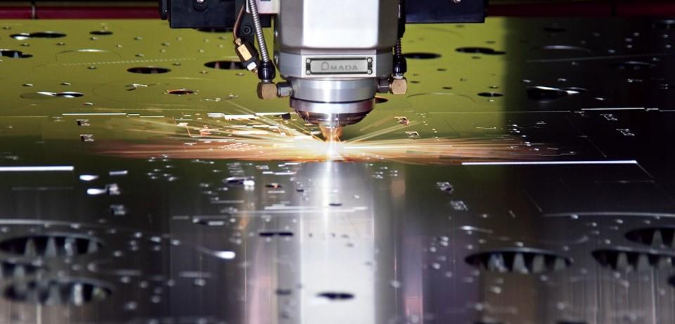
Machine programmers who think of the big picture, including sheet metal yield and how a nest affects downstream fabrication processing—can help boost manufacturing throughput and make life easier in the shop. Images: Amada
Do your receive performance reports showing abysmally low green-light-on time? For some unfiltered truth, head out to the shop floor. You might find a few tired employees at the shake-and-break station near your stand-alone fiber laser.
You might see unexpected downtime at your automated laser cutting center, its part-takeout automation stuck on a particular part. Your punch/laser combo unit might be down more than you expect, too, with technicians looking to eliminate part quality issues after clamp repositioning.
You might see a press brake setup that has far too many tryout parts. You talk to the operator to find he just can’t gauge the part steadily. You look at the cut blanks stacked neatly near the brake, look closer at the edges, and see the remains of a broken microtab. You then walk to welding and see two sheets in a fixture. The mated edges will soon be fused and covered in weld metal. In this case, the microtabs wouldn’t have negatively affected the weld, yet the parts are still deburred to a perfect finish. Why were those blanks in welding deburred and yet the blanks in bending weren’t?
All this points back to what has become the keystone in modern sheet metal fabrication: programming, including the nesting for and programming of the shop’s primary cutting operation (see Figure 1). Those with ownership over programming think not just about material yield, but also about what happens to a part during and after punching or laser cutting.
By knowing all the processes that go into bringing a cut blank to forming, welding, and beyond, programmers can develop strategies that help make those tasks as easy and repeatable as possible. Put another way, good programmers—people with a strong sense of ownership over their work who can balance the fabricator’s quest for high material yield with the needs of downstream operations—can help make a struggling shop more successful.
In a perfect world, every cut piece would sit perfectly in a nest without a microtab so that workers or automation could easily lift each workpiece out of the sheet and send it downstream, no deburring required.
Several factors, though, push programmers toward microtabbing. The first and most obvious is part geometry. On a laser cutting machine, some part shapes (especially the small ones) simply can’t sit loose on a sheet without falling through the slats.
No matter the part’s shape, though, programmers rely on microtabs for part stability, and the best do so by thinking about not just what happens on the cutting table but also downstream. For instance, a shop with tired personnel at the part-breakout table likely has an overtabbing problem.
The perimeter of parts 0.25 in. thick and more generally doesn’t need to be tabbed at all. Think about the game of Operation. When you lift a thick piece through the hole and mistakenly let it go, it lands on the hole edges but doesn’t fall through. The same interaction is at play in thicker sheet metal and plate. The thickness alone helps lock the part into the skeleton.
When you see part-breakout employees with suction or magnetic devices lifting 0.25-in. or thicker pieces, they’re effectively playing Operation. On their most productive days, they simply lift nontabbed parts perfectly straight out of the skeleton. In material 0.375 in. or thicker, even just one tab, no matter how narrow, can make the part virtually impossible to break out of the skeleton.
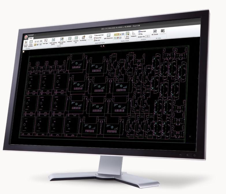
Figure 1 Those with ownership over programming think of all the details, including the size and placement of microtabs, part orientation relative to the slats, skeletal integrity, and how tab placement affects downstream operations.
Under the right circumstances, one tab generally will be enough to keep most sheet metal parts in the skeleton. Using a magnet or other lifting device, you should be able to pull up and, after making a slight back-and-forth motion, hear the microtab snap as the part breaks free.
If circumstances require you to tab the part twice, the kerf around that piece needs to be wide enough to allow you to twist that piece back and forth to break both tabs. Having more than three microtabs in one part is a red flag. Unusual circumstances aside, more than likely you’re using too many tabs.
When you do tab, make sure you’re following a practice that’s consistent across the shop. Some operations use standard tab widths for different material thicknesses; again, thicker material calls for narrower tabs, considering the entire material thickness adds to the volume (and holding power) of each tab. Some use formulas that optimize tabbing for specific part mixes. Whatever that standard practice is, it should take into account not only cutting stability, but also downstream processing.
Say that tab is on the edge that will slide against a backgauge on a press brake. The burr left after breaking the microtab can cause the part to rock slightly as the operator presses the edge against the backgauge. Such inconsistency can cause a lot of bending headaches.
If you’ve determined you absolutely need that microtab, and you don’t want to resort to adding a secondary deburring process, you have two alternatives. You could move that tab elsewhere on the part perimeter, such as to an edge that will be welded. Or, if the part design allows (both functionally and cosmetically), you could design the tab so it breaks inward, leaving an ever-so-small divot on the part edge and creating a flat gauging surface for the brake operator.
Of course, before deciding where the tab should go or how that tab should break, first ask if you need the tab at all. Is there a way to arrange a nest or sequence the cutting to eliminate the need for that tab? Here’s where your nesting software’s collision avoidance comes into play.
Say you have a part that has internal geometries (slugs) prone to tip-ups, or a piece that tends to bow after being cut. You could use microtabbing, but there’s probably a simpler, much more effective solution.
When programming a flying-optic laser, you can use collision avoidance to ensure the head never traverses over a certain coordinate where it’s already been, and sequence certain tip-up-prone cut geometries last. For instance, the laser head might cut a piece’s internal geometries first, then take a new path toward the part perimeter, not over previously cut areas where tipped-up slugs could cause a crash.
A part’s relation to the slats plays a big role too. If you have a long, skinny part, you generally want to nest it in the X direction so it lies across multiple slats (see Figure 2). This means, even if you have poor-quality steel that bows up after cutting, the piece will remain securely sitting on the cutting table.
Some software allows you to add slat locations to the nest layout so you can see plainly where the slats sit in relation to the parts you’re cutting. If you see a part lying over two slats but you need it to lie over three, you can make the change.
Figure 2 So that they lie across multiple slats, long parts are oriented in the X direction.
A topnotch programmer today needs to consider not just part stability during cutting, but how the material moves throughout the entire cutting process. And the nature of that movement can vary tremendously, especially in operations that have both stand-alone and automated cutting systems.
In stand-alone flying-optic lasers, material movement is minimal. The sheet shuttles into the work envelope, the machine calibrates (establishing the 0,0 coordinate), and the laser head commences cutting. After cutting, the machine shuttles the cut sheet out to the offloading station.
The cutting program still needs to ensure part stability, with the head avoiding potential tip-ups and collisions. Assist gas flow can have an effect in some environments, too, causing parts to tip as the head rises at the end of a cut. To prevent this, modern machines shut the assist gas off abruptly as the head retracts and moves to the next coordinate. If the machine doesn’t do this effectively, and if the head needs to traverse over the previously cut part, a programmer can always put a brief dwell (as an M code in the program) before traversing over that part.
Regardless, with a stand-alone flying-optic laser, the shuttle table moves but the sheet itself doesn’t, at least until employees at the breakout table start removing parts (which, again, programmers should factor into their nesting and tabbing strategy). Because the sheet itself doesn’t move, ensuring part stability and effective removal are relatively straightforward.
Laser automation introduces additional variables, and to understand them, it helps to know exactly how sheets and parts move to and from the cutting work envelope. The first level of automation moves sheets from a storage system to the cutting table, then removes the complete cut nest after cutting, either to a storage system cassette or an offload table for part sorting.
This usually entails a combination of suction cups for retrieving the material and forks, which slide in between the slats to lift and remove the cut sheet, both the skeleton and cut parts. The forks themselves should enter far enough below the sheet to avoid colliding with any part or internal-geometry (slug) tip-downs between the slats. In most cases, the forks rise and lift the sheet without incident, but severe part tips or distortion (especially with large parts) can create issues as the forks lift and transport that cut nest of parts to its destination.
To prevent this, a programmer might be tempted to add more microtabs, but again, adding those microtabs could also add processing costs and general headaches downstream. It’s usually best to pinpoint the root causes of that tipping and distortion. Rather than adding microtabs, it might be a lot easier to simply reposition or reorient a part in a nest layout (or sometimes change how slats are spaced across the table) so that parts remain stable and don’t tip in the first place.
When automated part removal and sorting enter into the picture, the variables increase. Modern options include intelligent suction grippers on a mechanized system (see Figure 3) or at the end of a robot arm. Using a variety of cup sizes, these grippers can grasp the part firmly and lift it cleanly out of the nest. Instead of a human, the automation now is playing the game of Operation.
That said, some part geometries can create part-removal challenges, especially when it comes to acute angles. A part with an acute angle has a greater chance of catching or otherwise interfering with the skeleton. In this case, the laser can perform a skeleton-destruct (or slug-destruct) sequence, removing the skeletal metal near the part’s acute angle so that when the grippers remove the part, all’s clear.
In other snag-prone situations, the laser can cut slits into the skeleton in strategic locations. Those slits make the skeletal web less rigid and allow it to move away from the part as grippers lift the part out of the sheet.
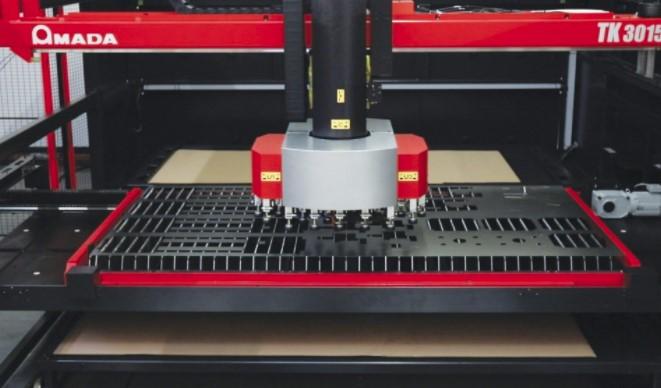
Figure 3 With the right nesting and programming strategy, part removal systems should be able to lift parts cleanly out of the nest.
Skeleton-destruct sequences can be taken a step further and, in some instances, eliminate the need for suction-based part removal. Consider a scenario where the laser cuts a nest of several large rectangular parts, then destroys the remaining skeleton, cutting tiny triangles that fall through the slats and through a scrap chute. Forks then enter from below, lift the large workpieces, then transfer them to a conveyor that transports the work downstream.
The practicality of this approach depends on the part mix, volumes, and the size and shape of your parts (it’s far more common when dealing with large workpieces in high volumes). Regardless, the approach exemplifies holistic thinking. From a pure cutting-inches-per-minute perspective, destroying the skeleton in such a way might seem extraordinarily wasteful. But think of the benefits. Scrap is gathered automatically in easy-to-move containers. Tabbing becomes unnecessary, and you eliminate the need to move a skeleton with loose parts.
Microtabs play several roles in punching. Like in a stand-alone laser, tabs keep parts secure as they emerge from the machine, if they haven’t already been parted out and sent down a chute. But unlike in laser cutting, tabs as well as the skeleton’s webs work in concert to ensure skeletal integrity as the sheet moves throughout the cutting cycle. A weak skeleton can wreak havoc.
The locations of tabs, slugs, and skeletal components are especially critical to ensure parts don’t catch on the skeleton but instead fall consistently down the chute. Common-line cutting is a common strategy here; a small part in a cluster of common-line-cut workpieces has a better chance of falling freely, with no skeleton in its way. Alternatively, this might call for skeletal- or slug-destruct sequences and strategic tabbing. The bottom line: When the last microtab is cut, nothing should prevent that part from falling.
Again, because the sheet is moving, you have no choice but to ensure parts are tabbed in place during the cutting cycle. This might seem like a disadvantage, but in the context of automation, it’s actually a big advantage. In fact, there’s a good reason why part-takeout automation is far more common in the punching and punch/laser combo arena.
New laser beam control technologies are changing the game (more on this later), but in traditional laser cutting, untabbed parts need to travel “loose” within the skeleton through several positions after cutting before reaching the part-picking automation.
Not so with punching or the punch/laser combo system automation. The sheet is clamped and is moved under the turret and laser head. Cutting commences and microjoints hold the work in place. Then comes the part-removal process. In some situations, a tool dedicated to microjoint removal cuts the tabs just before the gripper comes in to remove the part. In other cases, suctions can actually grip and secure the part before the laser removes the final microjoints. The laser cuts and the part is securely lifted away. Never does the part float loose in a sheet.
Many overlook one key variable: the condition of the cutting table. This includes the brush table for punching and punch/laser combos as well as table slats for laser cutting (see Figure 4). Slag buildup on your slats does more than just look bad. It can actually change the position of the sheet and part.
Imagine that the laser cuts a part. The shuttle table moves to the part offloading station, and a gripper commences its cycle. Problem is, it fails to pick up the part. Why? It goes back to those dirty slats. Slag doesn’t spread evenly, of course. Some slat tips have more slag than others, which makes anything sitting on top of them uneven.
After the laser cuts the part, it’s just floating in the skeleton and sitting unevenly on those dirty slats. The automation “thinks” the piece is at a certain height when it’s not. And because the workpiece is uneven, it’s more likely to catch against the skeleton. Again, it’s the game of Operation, and with dirty slats, part-removal automation has a greater chance of losing. The solution is obvious: Clean your slats on a regular schedule.
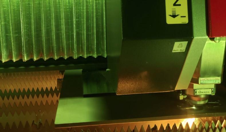
Figure 4 A laser begins cutting over a set of new, clean copper slats. Reliable laser cutting requires regular slat cleaning, especially in automated systems. Excessive slag buildup can change the position of the sheet and cut part, which in turn can affect the reliability of part-removal automation.
In a punching or punch/laser combo setup, the cutting table condition can be just as important. In fact, ignoring the table condition might prevent the programmer from strategies that would result in greater material utilization.
This includes the old trick of clamp repositioning so that the programmer can nest parts “under the clamps.” To reposition a sheet, repositioning pads with plungers reach out and hold the sheet stationary as the clamps release and reposition themselves. At the end of the operation, you retrieve the parts, only to find a small step on a part edge. It looks like there was a problem with clamp repositioning.
You check the plungers on the repositioning pads; they aren’t worn. They’re air-activated, so you check the air pressure, which seems spot on. So the plungers should be getting a firm grip.
Before pointing fingers at programming and making it a policy not to include clamp repositioning, check the condition of your brush table. A brush table worn down 3 mm in certain areas can be enough to cause an issue. When the clamps release the sheet, the sheet sags—only a bit, but enough so that when the clamps re-engage in their new position, they push the sheet ever so slightly. That’s enough to create a mismatch between where the sheet is and where the program thinks it is.
All these real-world shop conditions—the nature of automation in your shop, part removal, the condition of your machines—should help you build rules that shape your programming strategy. With input from operators, part-removal employees, and others, you can build programs that will help make their lives easier.
You can opt for sequencing that avoids head collisions, and you can tell software whether certain kinds of parts need to sit on however many slats on the laser cutting bed. If certain parts will be difficult for takeout automation, you can tell software to nest them in groups that takeout automation can then grasp.
For instance, if you’re cutting a panel with a large window, you might be able to fit a dozen small brackets in that window, and they can all be tabbed and secured for an automated gripper to grasp, move, and stack—even in an unattended operation over the weekend.
Such unattended automation in laser cutting, complete with part stacking, is sure to become more common in the years to come, and this has a lot to do with technology behind the laser beam itself. Various beam width and manipulation techniques are creating wider kerfs that help make automated part removal far more robust and reliable.
Some of the latest beam control technologies can create kerf widths two or three times wider than was possible before (see Figure 5). For part-removal automation (and manual part-removal personnel, for that matter), this makes that game of Operation easier than ever.
Your slats are clean. Your brush table is far from worn. Your strategic programming—the use of collision avoidance, part orientation, grain restraints for bending or cosmetics, and more—has helped streamline flow and make life on the shop floor much more predictable.
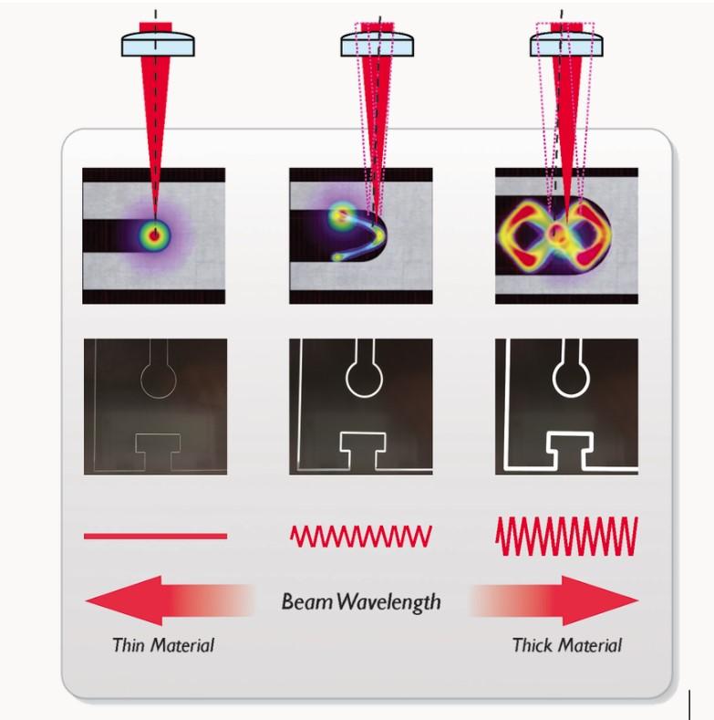
Figure 5 New beam control technologies fine-tune the kerf width for the application, such as wider kerfs for part-removal automation.
As a good programmer, you take pride in achieving high yields. At the same time, you’ve put good rules in place so that software nests in a fashion that best suits your operation. You minimize your time tweaking dynamic nests (considering that, unlike static nests, you won’t likely see that group of parts again), though you’ve established rule preferences that give you a dynamic nest that doesn’t need to be tweaked anyway. Sure, through part orientation constraints or other restrictions, you might sacrifice a little material yield to ensure process stability with high green-light-on time, but it’s well worth it.
Then material prices skyrocket. The largest expense on the balance sheet just got even larger. As a programmer, you’re at the center of a companywide debate. Managers and purchasers want maximum yield on every sheet and are quite happy to switch to cheaper material. Meanwhile, shop personnel want only the material they need now—no unneeded filler parts just to fill a nest, please—and they want good, laser-flat sheet.
To mitigate this, you as the programmer communicate with shop management and purchasing about the value of good material. A few pennies saved per ton will be far outweighed by the hours spent on the floor dealing with distortion and other unpredictable characteristics of poor sheet stock.
Better stock can push throughput through the roof in various ways. For instance, say you have a sheet full of long, thin parts. A programmer with good material will likely want to nest them in the X direction, across the slats, and perform common-line cutting. Those common cuts have a triple benefit: They shorten the cutting time dramatically (cutting one line gives you two part edges), increase material yield, and make downstream processing easier. The parts are easy to remove from the nest. And with no microjoints, they don’t require deburring, nor do they open the door to gauging problems at the press brake. Of course, if you have subpar material and your parts bow, you might need to add microjoints, so all those downstream processing benefits go out the window.
To meet the demand for increased yield while balancing the needs of the shop floor, you ask your ERP and scheduling personnel for an annual usage estimate. You use that to govern your filler part usage and remnant management strategy. Sure, 100 of a certain part might fit perfectly onto a sheet, but if that gives you enough to last two years, they aren’t good filler parts. On the other hand, if an extra 50 of a certain part has a good chance of being utilized over the next two weeks, cutting and storing those filler parts might make sense.
These decisions can vary greatly and depend largely on the needs and nature of the operation. Regardless, good programmers can’t just bury their head in front of a computer screen. The better they know the shop and what happens to their parts during and after cutting, the more they help improve flow and boost throughput, from raw stock to the shipping dock.


The Fabricator is North America's leading magazine for the metal forming and fabricating industry. The magazine delivers the news, technical articles, and case histories that enable fabricators to do their jobs more efficiently. The Fabricator has served the industry since 1970.
start your free subscription
Easily access valuable industry resources now with full access to the digital edition of The Fabricator.

Easily access valuable industry resources now with full access to the digital edition of The Welder.

Easily access valuable industry resources now with full access to the digital edition of The Tube and Pipe Journal.

Easily access valuable industry resources now with full access to the digital edition of The Fabricator en Español.
In this episode of The Fabricator Podcast, Caleb Chamberlain, co-founder and CEO of OSH Cut, discusses his company’s...


