


President
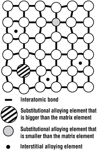
Figure 1. Small gaps between atoms, called interstices, are where small elements like carbon and nitrogen fit. As the alloying increases, the straining in the atomic lattice increases, requiring more force to deform the workpiece, thereby increasing the strength.
Any pure element is soft and ductile. This is why wedding bands are never made of pure 24-karat gold. They are usually made of 12-karat gold, which is 50 percent gold and 50 percent “impurities.”
Similarly, pure iron is extremely soft and is not used in structural applications. However, iron with up to 2 percent carbon is known as steel, making it the most widely used engineered material in the world.
Microscopically, pure iron can be thought of as a 3-D lattice of stacked billiard balls. For most low-carbon steels, more than 99 percent of the microstructure is still iron, with all other elements combining to form typically less than 1 percent of the overall composition. No matter how well the billiard balls are packed, some gaps will always be found in between. These small gaps are known as interstices. The smallest elements like carbon and nitrogen can fit in these gaps. Larger atoms like manganese, magnesium, silicon, and phosphorus substitute for iron in the lattice (see Figure 1).
When a very small fraction of the interstices in between the iron lattice is occupied by carbon atoms, this interstitial-free (IF) steel is said to have a microstructure of ferrite. Ferrite has a body-centered cubic (BCC) crystal structure (see Figure 2a). Ferrite is a microstructural phase that is soft, ductile, and similar to pure iron.
There is a limit on how much carbon can fit in the gaps in the ferrite structure: 0.02 percent carbon at 1,340 degrees F (725 degrees C), but dropping to 0.006 percent (60 PPM) carbon at room temperature.
The gaps are a little larger in a phase known as austenite, which has a face-centered cubic (FCC) crystal structure (see Figure 2b). At around 2,100 degrees F (1,150 degrees C), up to 2 percent carbon can fit into the austenite microstructure.
As the steel slowly cools from this temperature and carbon is forced out of solution, the austenite transforms into a combination of ferrite and another phase called cementite, also known as iron carbide, which has the chemical composition of Fe3C. The amount of cementite that forms is a function of how much carbon is in the steel. Because ferrite cannot contain more than about 60 PPM carbon at room temperature, the rest of the carbon winds up as cementite.
Unlike ferrite, cementite has the characteristics of a ceramic: very hard and brittle, with low toughness and little resistance to crack initiation and propagation. The mixture of ferrite and cementite is called pearlite, named because it looks like mother of pearl under a microscope, with alternating layers of ferrite and cementite.
With faster cooling, different dynamics occur. Above a critical cooling rate (typically faster than 86 degrees F per second, but dependent on the alloy), the excess carbon of the FCC austenite does not have time to diffuse out of the crystal structure and form cementite. Instead, the carbon is trapped in with the now nearly pure iron and forced into the interstitial locations that are not large enough to accommodate the carbon atoms. This distorts and strains the crystal matrix into a body-centered tetragonal (BCT) structure (see Figure 2c), forming a hard phase called martensite.
At higher carbon levels, more carbon is frozen into the BCT structure, further straining the crystal matrix. This is why the hardness of martensite increases with carbon level. The volume of the BCT martensite structure is larger than that of the FCC austenite, so the freshly transformed martensite is compressed by the surrounding matrix.
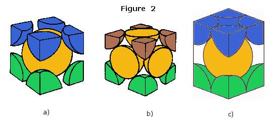
Figures 2a, 2b, and 2c. These are examples of crystallographic structures. The different colors represent different layers of iron atoms. The size of the iron atoms is essentially the same in each of these structures. The only differences are the density, dimensions, and sizes of the gaps within these unit cells. The smallest elements like carbon can fit into these gaps. Ferrite (a) has a body-centered cubic crystal structure. Austenite (b) has a face-centered cubic crystal structure. Martensite (c) has a body-centered tetragonal crystal structure.
If martensite is heated, carbon has the opportunity to diffuse out from the BCT structure, reducing the distortion of the crystal matrix, leading to decreased hardness and increased toughness. This heat treatment produces a microstructure of ferrite and iron carbide (Fe3C) called tempered martensite. The highly strained martensitic matrix results in an increased amount of Fe3C nucleation sites in tempered martensite, which leads to a more dispersed distribution of Fe3C than seen in the lamellar (layered) structure of pearlite. The volume of the BCC ferrite is smaller than that of the BCT martensite, so that when martensite is tempered, some of the residual martensite compression stresses from the austenite-to-martensite transition are relieved.
Retained austenite is the term given to austenite that does not transform to martensite during quenching. The amount of retained austenite is a function of several factors, including carbon content and alloying to specifically promote retention of the austenitic structure. For example, austenitic stainless steels like 304 and 316 are engineered to be fully austenitic at room temperature.
Bainite is another microstructure that can form when austenite is cooled. It typically consists of a combination of ferrite, cementite, and retained austenite. Because the cooling rate to form bainite is slower than the cooling rate needed to form martensite, carbon has some opportunity to diffuse out of the FCC austenite, allowing for the formation of BCC ferrite. The remaining austenite is enriched with carbon, which leads to cementite precipitation. However, the slow cooling rates that produce the flat-layered, brittle structure of pearlite do not exist; the higher cooling rates needed to produce bainite give the harder components of the microstructure enough energy to transform into a more rounded shape.
Bainitic microstructures have the best balance of strength and ductility. The cooling rate is fast enough to increase the strength, while the rounded hard microstructural constituents are not as prone to crack initiation and propagation than if they were flat and elongated. The strength-toughness balance is why an increasing number of automotive wheels and suspension arms are being made from bainitic steels.
(Figure 1 is taken from http://image.thefabricator.com/a/stamping-101-material-guidelines-atom-interstices.gif)


The Fabricator is North America's leading magazine for the metal forming and fabricating industry. The magazine delivers the news, technical articles, and case histories that enable fabricators to do their jobs more efficiently. The Fabricator has served the industry since 1970.
start your free subscription
Easily access valuable industry resources now with full access to the digital edition of The Fabricator.

Easily access valuable industry resources now with full access to the digital edition of The Welder.

Easily access valuable industry resources now with full access to the digital edition of The Tube and Pipe Journal.

Easily access valuable industry resources now with full access to the digital edition of The Fabricator en Español.
In this episode of The Fabricator Podcast, Caleb Chamberlain, co-founder and CEO of OSH Cut, discusses his company’s...


