


Principal Engineer, Gas Equipment
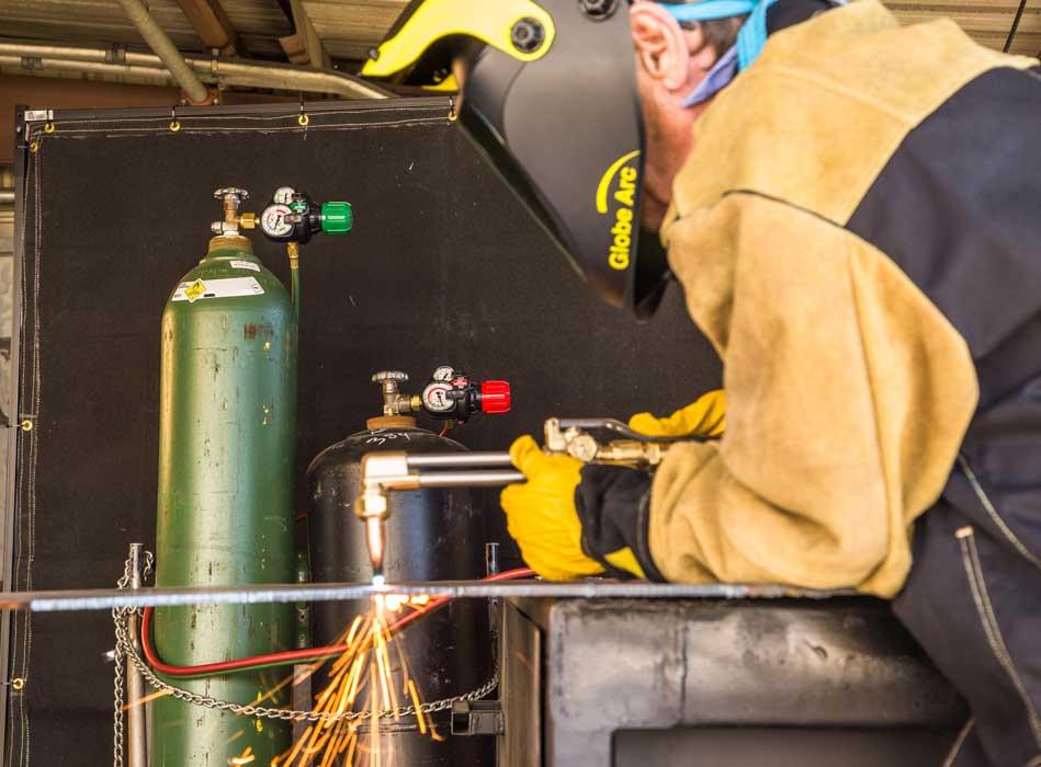
Figure 1
The gas pressure regulators on the cylinders may not be the first thing that you notice, but the fabricator has his eye on them. Differences in gauge size and color-coding enable him to evaluate gas flow and cylinder contents, even from a distance.
In the process of oxyfuel cutting, preheat flames from a cutting torch bring a piece of steel to a cherry red color. Once kindling temperature is reached, applying pressure to the torch’s oxygen lever releases a stream of pure oxygen, initiating rapid oxidation. This is oxyfuel cutting.
As operators focus on the cut path, they rarely think twice about the regulators that are supplying oxygen and fuel to their torch. What’s happening inside a regulator that enables it to provide for a trouble-free cutting process? How do regulators help provide safe, consistent operation? Can a regulator design even enhance operator experience?
The technical definition of a regulator, as defined by ISO regulator standard 2503 (Section 3.12), is a device for regulating a generally variable inlet pressure to an outlet pressure that is as constant as possible. Inlet pressure sources include high-pressure cylinders, liquid cylinders, bulk supply systems, and air compressors. Outlet pressure management is required for oxyfuel torches with cutting, heating, and welding attachments; welding systems; and plasma cutting operations. (This typically involves air or nitrogen cylinders used for field fabrication.)
Regulators come in many different forms, depending on performance needs, size constraints, maximum inlet pressure, type of gas being used, purity requirements, and even personal “look and feel” preferences (see Figure 1). Modern regulator design can be traced back to William Stettner, the founder of Victor, who developed his first product in 1913 after losing an eye in a regulator explosion. As Figure 2 shows, his design has withstood the test of time, with many modern regulators retaining a similar look. Figure 3 highlights the major internal components of a regulator, and color codes the high- and low-pressure areas.
Within the regulator, the diaphragm is the sensing element that does most of the hard work—which is to open and close the seat that controls gas flow from the high- to low-pressure chambers of the regulator. Gas flow control is a three-step cycle:
During use, the regulator is constantly refilling itself to replace the gas being withdrawn from the low-pressure chamber (see Figure 4). What the operator perceives as constant delivery pressure is actually continuous action inside the regulator to maintain equilibrium.
Because the diaphragm and seat do most of the work, they also are the two main components that drive flow performance in a regulator. Diaphragms often are constructed from elastomeric materials, such as neoprene, as well as from metals, such as thin stainless steel sheet. A neoprene elastomer diaphragm has incredible flexibility, making it suitable for use as a regulator diaphragm, where it’s constantly moving to open and close the regulator seat. However, any elastomer material naturally degrades over time, is prone to absorbing contaminants, and is susceptible to performance impairment caused by extreme high or low operating temperatures. Stainless steel generally is perceived as a more durable material. It does not rust or absorb contaminants and is nearly impervious to extreme temperatures. But like any metal, it can only go through so many cycles of flex movement before its grain structure degrades, causing a loss of mechanical properties.
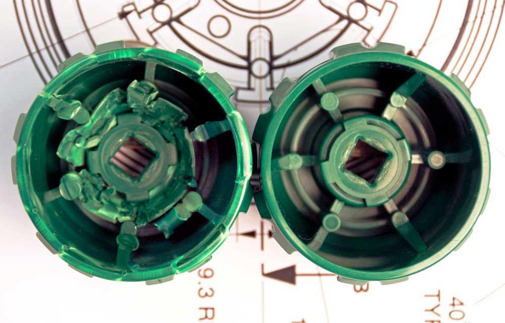
Underwriters Laboratories (UL) standard 252 requires a stainless steel diaphragm to withstand 10,000 endurance cycles before it is considered safe, but elastomer diaphragms require 25,000 endurance cycles because of the inherent flexibility characteristics of an elastomer over steel. The perfect diaphragm would combine the durability of stainless steel with the flexibility of an elastomer for the best of both worlds. Newer diaphragm designs are looking to surpass current performance expectations (see Figure 5).
The physical size of the diaphragm is important to performance, as a larger surface area provides greater sensitivity to pressure changes, and it can allow for greater flow output. However, a larger diaphragm means a physically larger regulator, which can add size and weight to the portable regulators, which have to be attached manually to cylinders. Also, many applications simply don’t need ultrahigh performance and sensitivity, so a regulator made for extreme performance may be overkill (and often significantly more expensive).
Seat orifice size also is very important. A bigger orifice flows more, but bigger isn’t necessarily better, as it can lead to more pressure drop and more “rise” (see Rise Explained sidebar). Seat material choice is critical to a regulator design, and many different materials are used in their construction. Soft seat materials, such as urethane, provide excellent performance at low pressures and are very forgiving of contaminants and surface finish imperfections. However, soft seats move under pressure, so performance can sometimes seem sluggish, especially at low temperatures. Hard seat materials, such as PCTFE or nylon, offer more precise response, can handle high inlet pressures, and work well in cold temperatures. However, these can be very susceptible to surface imperfections and contaminants, so they often need to be encapsulated for cleanliness and require more critical machining and surface finishes.
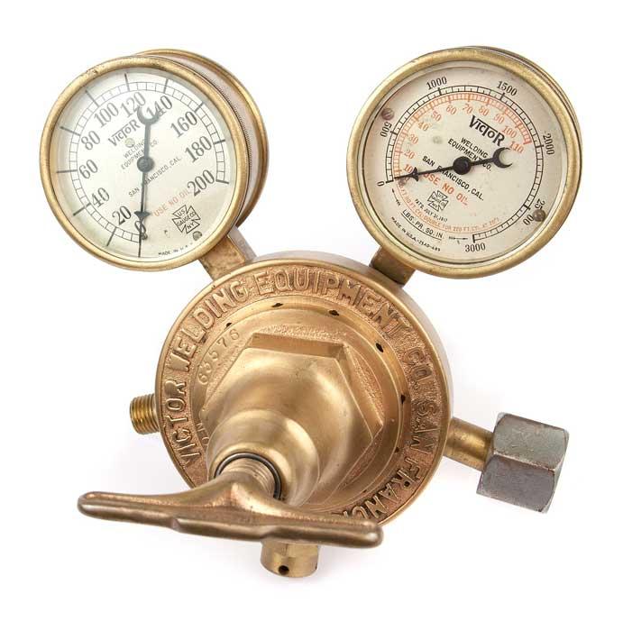
Figure 2
While current regulators use more modern materials, their look is strikingly similar to a design patented in 1917.
A regulator is considered to have good performance when it consistently delivers the pressure required for the application, as set by the operator. It must continue to deliver the set pressure no matter what application demands are placed on it and for as much of the cylinder contents as possible. Using a size 3 acetylene cutting tip as an example, a standard tip chart shows that this application requires 40 to 45 PSIG (210 to 240 SCFH) of cutting oxygen and 5 to 10 PSIG of preheat oxygen. If the operator sets the regulator to deliver 40 PSIG, the operator should expect 40 PSIG when the cutting oxygen lever is depressed. If the pressure drops to 35 PSIG, that’s poor performance.
A good regulator delivers the set flow rates from extremely heavy flows (such as a large cutting tip or multiflame heating attachment) to extremely small flows (such as a size 0 welding tip, which requires just 3 to 5 PSIG of oxygen). To evaluate regulator performance, look at a flow data graph. A good-performing regulator has a nearly flat line, meaning that it delivers close to the set pressure across its entire flow range. In contrast, delivery pressure from a poor-performing regulator may start out flat at very low flows but then arc rapidly down as flow demand increases. This delivery pressure drop can have serious negative consequences to application performance.
A premium regulator can provide decades of trouble-free performance, but even the best regulator wears eventually. Performance issues generally fall into one of five areas: seat failure (from contamination and wear); diaphragm failure (rips, tears, or cracks); gauge failures (needle jumps from impact damage, broken housings, or leaks); leaking connections (threads become contaminated or damaged); and “singing” or “buzzing” (when the seat and diaphragm get out of sync because of vibration dampening). A repair technician can install OEM replacement components to solve these problems, and a well-designed regulator will be designed for easy field repair.
Around 2009 a new regulator design was introduced that incorporated several safety features that altered the way a regulator looked and functioned. These included impact-absorbing crumple zones built into the knob to help protect the regulator and operator in the event of a cylinder fall (see Figure 6), a regulator shape that protects gauges and other critical components, and a particle trap that robs contaminants of their explosive power to help prevent oxygen fires. As the high-pressure gas from the cylinder enters the regulator, a 90-degree turn suddenly redirects gas flow. However, instead of making the turn, heavier particles will tend to follow Newton’s first law and continue to flow into a small pocket—the particle trap—designed to capture them, robbing them of their explosive energy. Any lighter particles that can make the turn encounter a secondary diffuser, which helps to further disperse any remaining energy before they reach the sensitive regulator seat.
The level of safety delivered by patented features such as these helps to prevent accidents. Regulators also have seen exterior design changes that are aimed at minimizing operator errors.
For example, on many regulators the high- and low-pressure gauges are the same size and shape and have no distinguishing characteristics besides reading the actual pressure numbers on the face. This can make it difficult to tell them apart at a glance. Of the two gauges, the low-pressure (delivery) gauge can easily be considered more important, from both a process and safety perspective. For that reason, new regulators have oversized delivery pressure gauges, while the cylinder pressure gauges are smaller and set back.
Research shows that operators often judge pressure values by needle position rather than closely reading the gauge. Correspondingly, modern gauges use color-coding, such as green for full or good, yellow for partial or fair, and red for empty or danger, to help make needle position more intuitive and easier to follow. Even at a glance from 10 or 15 feet away, operators can easily evaluate delivery pressure and cylinder contents.
Modern regulator designs also have color-coding to indicate gas type, such as green for oxygen, red for acetylene, and orange for liquid propane, as well as distinct labeling and gauge faces that provide information on maximum pressures and other important product characteristics.
The characteristic of rise occurs when outlet pressure increases as inlet pressure decreases (typically as a result of cylinder contents emptying). Fuel gases such as acetylene and propane have very low cylinder pressures, and their cylinders largely permit consistent pressure and flow performance until the cylinder is just about empty. High-pressure gases, such as oxygen, nitrogen, and air, are a different story.
Here’s how rise works:
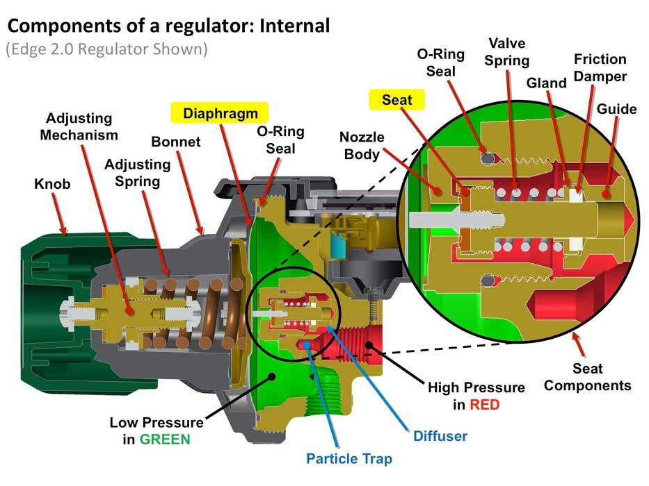
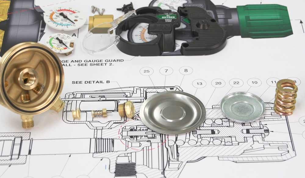
Figure 3
Internal components of a single-stage gas regulator are shown. This next-generation regulator also includes a particle trap and diffuser, both of which increase safety.
1. Inlet pressure applies a force on the regulator seat, essentially forcing it closed.
2. When the regulator is adjusted, the adjusting spring has to counter this force in addition to the force
it needs to achieve the required output pressure. If the inlet pressure is generating 15 pounds of force pushing the seat closed and the delivery pressure requires 40 lbs. of force to be obtained, then the adjusting spring is loaded to 15 lbs. plus the 40 lbs. required for delivery pressure, for a total net force of 55 lbs.3. As inlet pressure decreases, inlet force also decreases. This means the adjusting spring has less force
than it needs to overcome to obtain delivery pressure. So if the original 15 lbs. of force pushing the seat closed decreases to 10 lbs., then the force remaining for the delivery pressure now equals 45 lbs. (55 lbs. – 10 lbs.) instead of the original 40 lbs.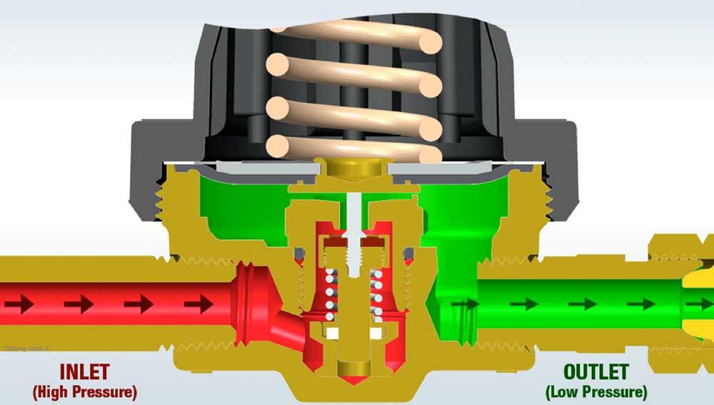
Figure 4
Adjusting the regulator knob opens gas flow to downstream equipment. When cutting commences, high-pressure gas refills the regulator’s low-pressure chamber, and a full cycle begins anew as long as demand is continuous.
4. As a result, delivery pressure increases slightly, and in a cutting application, the cutting flame be-
comes slightly oxidizing. The operator will need to stop cutting and readjust the regulator back to the original delivery pressure to achieve a neutral flame.

The Fabricator is North America's leading magazine for the metal forming and fabricating industry. The magazine delivers the news, technical articles, and case histories that enable fabricators to do their jobs more efficiently. The Fabricator has served the industry since 1970.
start your free subscription
Easily access valuable industry resources now with full access to the digital edition of The Fabricator.

Easily access valuable industry resources now with full access to the digital edition of The Welder.

Easily access valuable industry resources now with full access to the digital edition of The Tube and Pipe Journal.

Easily access valuable industry resources now with full access to the digital edition of The Fabricator en Español.
In this episode of The Fabricator Podcast, Caleb Chamberlain, co-founder and CEO of OSH Cut, discusses his company’s...


