


Director of Business Development and Product Management
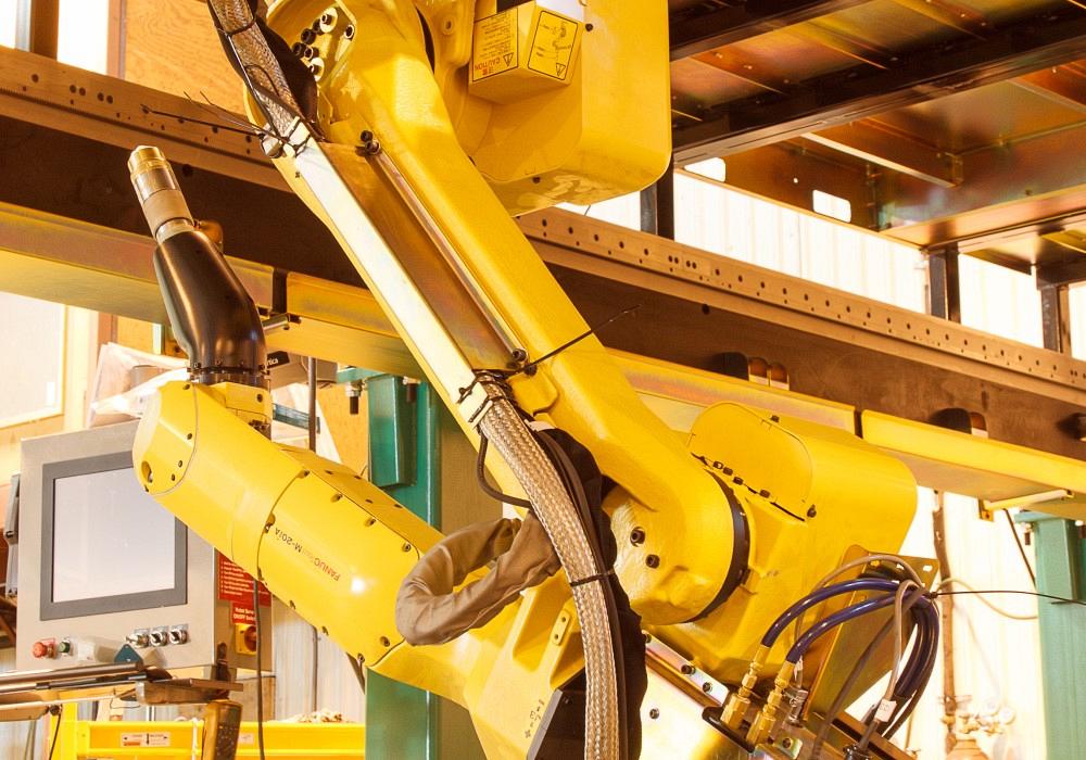
Integrating robotic plasma cutting takes more than attaching a torch at the end of a robot arm. Plasma cutting process knowledge is key. Hypertherm
Metal fabricators across the industry—in job shops, heavy machinery, shipbuilding, and structural steel—strive to meet demanding delivery expectations while exceeding quality requirements. They look continually for cost reductions, all while dealing with the ever-present issue of retaining skilled labor. The business isn’t easy.
Many of these concerns can be traced back to the manual processes still prevalent in the industry, especially when it comes to the fabrication of complex shapes like industrial vessel heads, curved structural steel components, and pipe and tube. Many fabricators spend 25% to 50% of their processing time on manual marking, quality control, and changeovers, while the actual cutting time—often performed with hand-held oxyfuel or plasma cutters—is only 10% to 20%.
In addition to the time such manual processes consume, many of these cuts are made around the wrong feature locations, dimensions, or tolerances, requiring significant secondary operations like grinding and rework or, even worse, scrapped materials. Many shops spend as much as 40% of overall processing time dedicated to this low-value effort and waste.
All this leads to the industry’s push toward automation. One shop that automated a manual torch cutting operation for complex, multiaxis parts implemented a robotic plasma cutting cell and, not surprisingly, saw dramatic benefits. The operation eliminated manual layout, and a job that took five people six hours to complete now was done in just 18 minutes with the robot.
While the benefits are obvious, implementing robotic plasma cutting takes more than just buying a robot and slapping on a plasma torch. If you’re considering robotic plasma cutting, be sure to take a holistic approach that looks at the entire value stream. Moreover, work with manufacturer-trained system integrators who know and understand plasma technology as well as the required system components and processes to make sure all requirements are integrated into the cell’s design.
Also consider the software, arguably one of the most important components of any robotic plasma cutting system. If you invest in a system but the software is either hard to use or takes a lot of expertise to run, or you find it takes an enormous amount of time to adapt the robot to plasma cutting and teach a cut path, you’ve just wasted a lot of money.
While robotic simulation software is common, effective robotic plasma cutting cells utilize offline robot programming software that will automate the robot path programming, identify and compensate for collisions, and integrate plasma cutting process knowledge. Incorporating deep plasma process knowledge is key. With such software, automating even the most complex robotic plasma cutting application will get a lot easier.
Plasma cutting complex, multiaxis shapes calls for unique torch geometries. Apply a torch geometry used in a typical X-Y application (see Figure 1) to a complex shape like a curved pressure vessel head, and you will increase the likelihood of collisions. For this reason, an acute-angle torch (with a “pointy” design) is better-suited for robotic shape cutting.
An acute-angle torch alone can’t avoid all types of collisions. Part programs also must incorporate changes to cut heights (that is, the torch tip must maintain a clearance of the workpiece) to avoid collisions (see Figure 2).
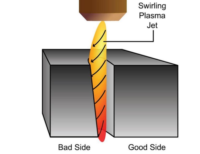
During cutting, plasma gas flows in a swirl direction down the torch body to the torch tip. This swirling action allows centrifugal force to pull heavy particles out of the gas column to the periphery of the nozzle bore and protect the torch components from high-temperature electrons flowing through. The plasma reaches a temperature of nearly 20,000 C, and the torch’s copper components melt at 1,100 C. Consumables need protection, and that insulated layer of heavy particles provides it.
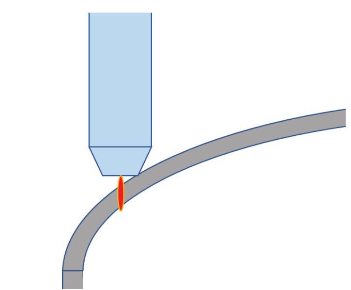
FIGURE 1. A standard torch body is designed for plate cutting. Using this same torch in multiaxis applications increases the chance of collisions with the workpiece.
The swirl makes one side of the cut hotter than the other side. Torches with a clockwise spinning gas generally put the hot side of the cut on the right-hand side of the arc (when viewed from overhead in the direction of cut). This means that process engineers work to optimize the good side of the cut and assume the bad side (to the left) will be scrap (see Figure 3).
Internal features need to be cut in the counterclockwise direction, with the hot side of the plasma creating a clean cut on the right (the part-edge side). Conversely, part perimeters need to be cut in a clockwise direction. If the torch cuts in the wrong direction, it creates a large taper in the cut profile and increases dross on the edge of your part. In essence, you’ll be putting the “good cut” on the scrap.
Note that most plasma plate cutting tables have process intelligence about the arc cutting direction built into the controller. But in the robotics arena, these details aren’t necessarily known or understood, and they are not already embedded in typical robot controllers—hence the importance of having offline robotic programming software with the embedded plasma process knowledge.
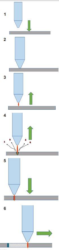
The torch motion for piercing metal has a direct impact on plasma cutting consumables. If a plasma torch pierces the plate at the cutting height—too close to the workpiece—the blowback of molten metal quickly damages the shield and the nozzle. This results in poor cut quality and short consumables life.
Again, rarely would this occur in a plate cutting application with a gantry because torch-height expertise is already built into the controller. An operator pushes a button to start the piercing sequence, which initiates a series of events to ensure a proper pierce height.
First, the torch performs a height-sensing routine, detecting the workpiece surface usually with an ohmic signal. Once the plate is located, the torch retracts from the plate to a transfer height, which is the optimal distance for the plasma arc to transfer to the workpiece. Once that plasma arc transfers, it can fully ramp up. At this point the torch moves to the piercing height, which is a safer distance from the workpiece, farther away from the blowback of molten material. The torch maintains this distance until the plasma arc has fully penetrated the plate. Once the pierce delay is complete, the torch moves down closer to the metal plate and initiates the cutting motion (see Figure 4).
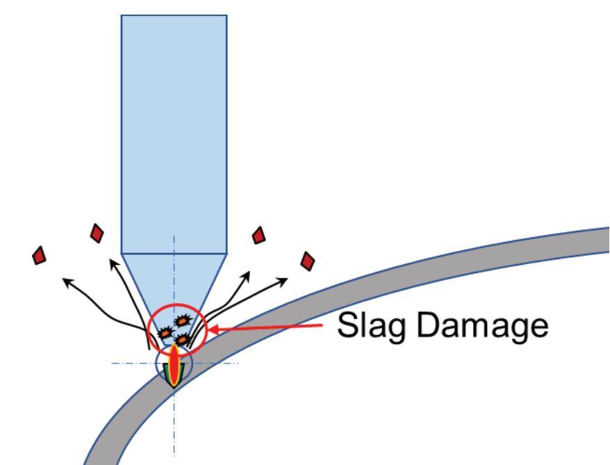
Again, all this intelligence usually is built into plasma controllers for plate cutting, but not into robotic controllers. Robotic cutting has another layer of complexity, too. Piercing at the wrong height is bad enough, but when cutting multiaxis shapes, the torch might not be in the optimal orientation to the workpiece and material thickness. If the torch is not perpendicular to the metal surface it’s piercing, it ends up cutting through a thicker cross section than needed, wasting consumable life. Moreover, piercing a contoured workpiece at the wrong orientation can put torch components too close to the workpiece surface, leaving it exposed to molten blowback and causing premature damage (see Figure 5).
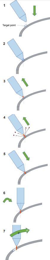
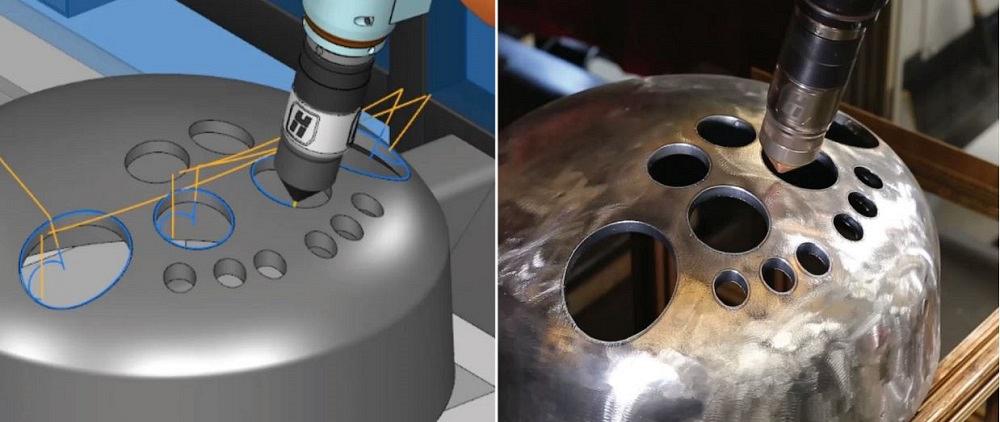
Consider a robotic plasma cutting application involving a curved pressure vessel head. Similar to plate cutting, the robotic torch should be placed perpendicular to the material surface to ensure the thinnest possible cross section for piercing. As the plasma torch approaches the workpiece, it will use height sensing until it locates the vessel surface and then retract along the torch axis to the transfer height. After the arc transfers, the torch retracts again along the torch axis to the piercing height, safely away from blowback (see Figure 6).
Once the pierce delay expires, the torch descends to the cut height. When working with contours, the torch either simultaneously or in separate steps rotates to the desired orientation for cutting. At that point the cutting sequence begins.
A robot is known as an overdetermined system. That is, it has various ways to reach the same point. This means that whatever or whoever teaches the robot to move must have a certain level of expertise, both when it comes to knowing robotic motion and the processing requirements for plasma cutting.
As much as teach pendants have evolved, certain tasks don’t lend themselves to teach pendant programming—specifically, tasks that involve a high mix of low-volume parts. The robot isn’t producing while it’s being taught, and the teaching itself can take hours or, for complex parts, even days.
Offline robotic programming software, designed with plasma cutting modules, will have this expertise already embedded within it (see Figure 7). This includes the cutting direction of the plasma gas, the initial height sensing, pierce sequencing, and cut speed optimization for the torch and plasma process.
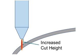
FIGURE 2. An acute (“pointy”) torch is better suited for robotic plasma cutting. But even with these torch geometries, it’s best practice to increase cutting heights to minimize the potential for a collision.
The software provides the robotics expertise required to program an overdetermined system. It manages singularities, or situations where the robot end effector (in this case, the plasma torch) can’t reach the workpiece; joint limits; overtravels; wrist flips; collision detection; external axis; and toolpath optimization. To start, a programmer imports a CAD file of the finished part into offline robotic programming software, then defines which edges to cut, as well as the pierce points and other parameters, accounting for collision and reach restrictions.
Some of the latest iterations of offline robotic software use what’s known as task-based offline programming. The method allows the programmer to generate cut paths automatically and select multiple contours at once. A programmer might choose an edge-path selector, which shows the cut path and direction, then choose to change the start and end point, as well as the direction and tilt of the plasma torch. The programming starts generically (independent of the brand of robotic arm or plasma system), then progresses to include specific robot models.
The resulting simulation can take into account everything in the robot cell, including elements like safety barriers, fixtures, and the plasma torch. It then illustrates any potential kinematic errors and collisions for the operator, who can then correct problems. For instance, a simulation might reveal a collision problem between two different cuts on a pressure vessel head. Each cut is at a different elevation along the head contour, so the rapid traverse between the cuts must account for the necessary clearance—a small detail that, when addressed before the job reaches the floor, helps eliminate headaches and waste.
The ever-present labor shortage combined with increasing customer demands have driven more fabricators toward robotic plasma cutting. Unfortunately, many dive in only to find more complications, especially when the people integrating the automation lack plasma cutting process knowledge. That path leads only to frustration.
Integrate plasma cutting knowledge from the start, and the situation changes. With plasma-process intelligence, the robot rotates and moves as needed to perform the most efficient pierces to prolong consumables life. It cuts in the correct direction and maneuvers to avoid any workpiece collisions. When following this path to automation, fabricators reap the rewards.
This article is based on “Advancements in 3D Robotic Plasma Cutting,” presented at the 2021 FABTECH conference.

The Fabricator is North America's leading magazine for the metal forming and fabricating industry. The magazine delivers the news, technical articles, and case histories that enable fabricators to do their jobs more efficiently. The Fabricator has served the industry since 1970.
start your free subscription
Easily access valuable industry resources now with full access to the digital edition of The Fabricator.

Easily access valuable industry resources now with full access to the digital edition of The Welder.

Easily access valuable industry resources now with full access to the digital edition of The Tube and Pipe Journal.

Easily access valuable industry resources now with full access to the digital edition of The Fabricator en Español.
In this episode of The Fabricator Podcast, Caleb Chamberlain, co-founder and CEO of OSH Cut, discusses his company’s...


